
Vehicle control device, vehicle control method, and storage medium

Active Publication Date: 2022-11-01
HONDA MOTOR CO LTD
View PDF8 Cites 0 Cited by
  • Summary
  • Abstract
  • Description
  • Claims
  • Application Information

AI Technical Summary

Benefits of technology

[0021]According to the aspects (1) to (5) and (11) to (14), by notifying a user of a user of a stop position of the vehicle, it is possible to realize efficient boarding. The user of the vehicle can be aware of a position at which the vehicle stops in a boarding area, can avoid unnecessary movement in the boarding area, and can shorten a boarding time. It is possible for the vehicle to recognize the user, and thus it is possible to realize efficient boarding by determining a stop position based on the position of the user of the vehicle.
[0022]According to the aspects (6) to (8), the user of the vehicle can easily and accurately be aware of an operation state of the own vehicle until the vehicle reaches the stop position.
[0023]According to the aspects (9) and (10), a person outside of the vehicle can easily be aware of that the vehicle is being automatically driven.

Problems solved by technology

The user of the vehicle may not be aware of a position in the boarding area at which the vehicle stops, and thus may be forced to move unnecessarily in the boarding area or it may take time to board the vehicle in some cases.

Method used


Image

  • Vehicle control device, vehicle control method, and storage medium
  • Vehicle control device, vehicle control method, and storage medium
  • Vehicle control device, vehicle control method, and storage medium

Examples


first embodiment

[Overall Configuration]

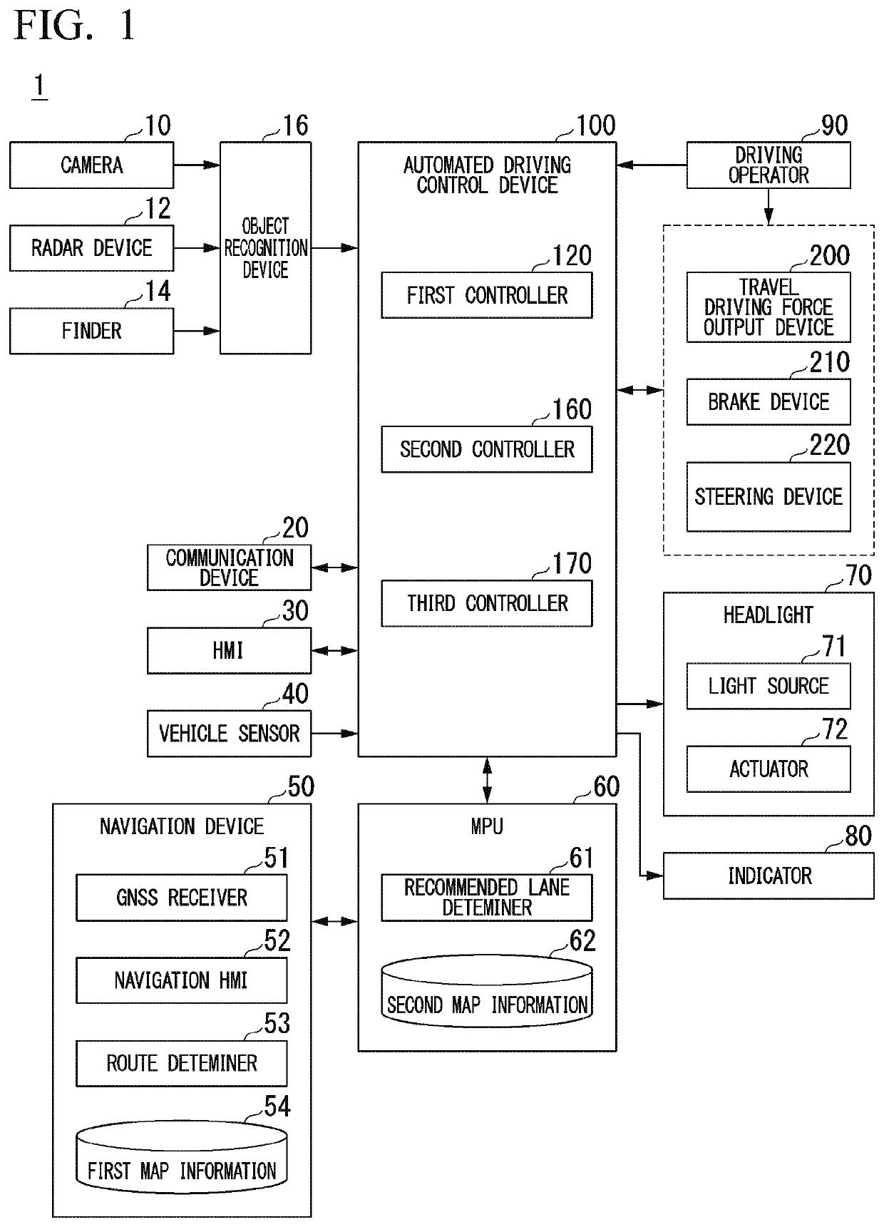
[0040]FIG. 1 is a diagram showing a configuration of a vehicle system 1 in which a vehicle control device according to a first embodiment is used.

[0041]A vehicle in which the vehicle system 1 is mounted is, for example, a vehicle such as a two-wheeled vehicle, a three-wheeled vehicle, or a four-wheeled vehicle. A driving source of the vehicle includes an internal combustion engine such as a diesel engine or a gasoline engine, an electric motor, and a combination thereof. The electric motor operates using power generated by a power generator connected to the internal combustion engine or power discharged from a secondary cell or a fuel cell.

[0042]The vehicle system 1 includes, for example, a camera 10, a radar device 12, a finder 14, an object recognition device 16, a communication device 20, a human machine interface (HMI) 30, a vehicle sensor 40, a navigation device 50, a map positioning unit (MPU) 60, a headlight 70, an indicator 80, a driving operator 90, a...

second embodiment

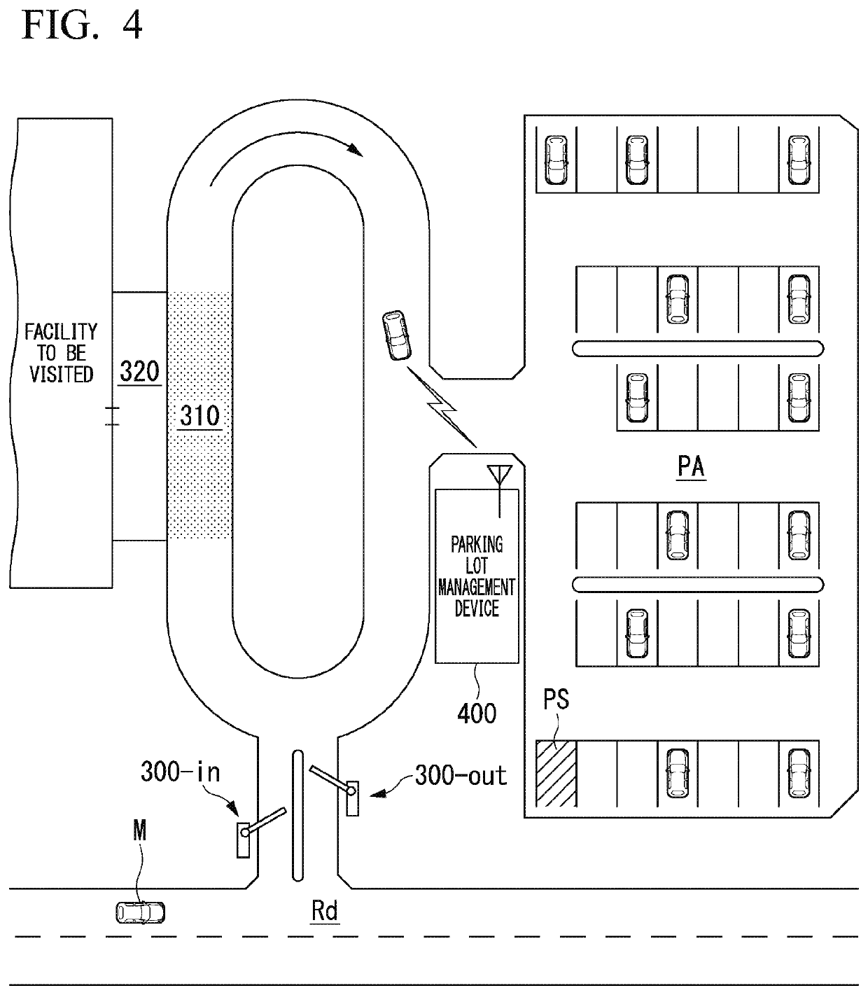
[0102]Hereinafter, a second embodiment will be described. An automated driving control device 100 according to the second embodiment differs from that of the first embodiment in that an operation mode of an indicator is changed based on a distance between the present position and the stop position of the own vehicle M in addition to the projection of the projection image indicating a stop position. Therefore, the drawings and description of the first embodiment can be referred to for the configuration and the like, and detailed description will be omitted.

[Operation Flow of Boarding Support Event]

[0103]FIG. 11 is a flowchart showing an example of an operation flow of a boarding support event of the automated driving control device 100 according to the second embodiment. The operation flow starts, for example, using detection of approach of the stop area 310 by the automated driving control device 100 as a trigger after the communication device 20 receives a pickup request transmitte...


PUM


Abstract

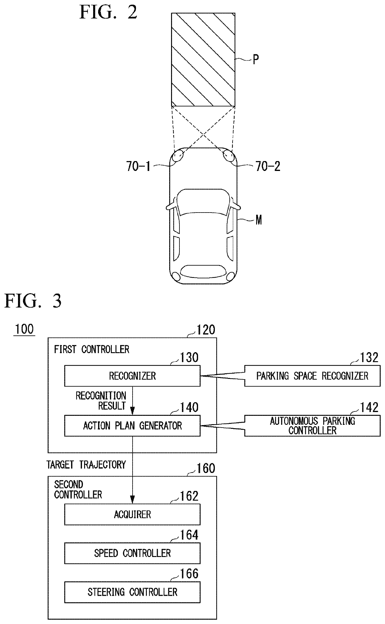
A vehicle control device mounted in a vehicle includes: a first recognizer configured to recognize a person near the vehicle; a first determiner configured to determine whether the person recognized by the first recognizer is a pre-registered user; and a controller configured to control a lighting device to project a projection image to a position for which a stop position of the vehicle is a criterion in a case where the first determiner determines that the person recognized by the first recognizer is the pre-registered user.

Description

CROSS-REFERENCE TO RELATED APPLICATION[0001]This application claims priority to and the benefit from Japanese Patent Application No. 2019-33238, filed on Feb. 26, 2019, the contents of which are hereby incorporated by reference into the present application.BACKGROUND OF THE INVENTIONField of the Invention[0002]The present invention relates to a vehicle control device, a vehicle control method, and a storage medium.Description of Related Art[0003]In recent years, studies of automated vehicle control have been conducted. In relation to this technology, devices recognizing a person who appears on a road and then notifying the person that a vehicle recognizes the region in which the person has appeared by radiating laser light at the feet of the person are known (for example, see Japanese Unexamined Patent Application, First Publication No. 2017-159882). Devices that support a parking operation of a vehicle by radiating line markers to a road surface near the vehicle are known (for exam...

Claims


Application Information

Patent Timeline
Patent Type & Authority Patents(United States)
IPC IPC(8): B60Q1/44H05B47/16H05B47/125
CPCB60Q1/442H05B47/125H05B47/16B60Q2400/50B60W30/06B60W40/00B60Q1/48B60Q1/46B60Q1/085B60Q1/245B60Q2300/314B60Q2300/45B60Q1/507B60Q1/543
Inventor MIMURA, YOSHITAKASHODA, YASUSHINOGUCHI, JUNPEIHARA, YUKIYAMANE, KATSUYASUYAMANAKA, HIROSHITAGUCHI, RYOMATAKADA, YUTASUGIHARA, CHIEMOTEGI, YUKISHIBAUCHI, TSUBASA
Owner HONDA MOTOR CO LTD
Learn More