Tool adapter quick-release structure

a tool adapter and quick-release technology, applied in the field of hand-held tools, can solve the problems of difficult to remove, difficult to install components, and often require replacement and repair of internal components, and achieve the effect of facilitating the operation and facilitating the installation of components

Active Publication Date: 2022-11-22
BASSO IND CORP
View PDF13 Cites 0 Cited by
  • Summary
  • Abstract
  • Description
  • Claims
  • Application Information

AI Technical Summary

Benefits of technology

[0005]A primary objective of the present invention is to provide a tool adapter quick-release structure in order to allow users to perform quick removal and to install components easily such that it is able to facilitate the operational needs.

Problems solved by technology

However, in terms of the design, the output axle of a traditional handheld tool or power tool is typically not equipped with the function allowing users to perform removal, repair or replacement of parts individually.
Consequently, after a long period of use of such tool, the internal components often require replacement and repair due to the problem of wear.
Nevertheless, since the operating element and the holding element adopt the threaded method of installation, it is not facilitated for removal.
As a result, due to the design of inconvenient removal, traditional handheld tools typically have the drawback of requiring the replacement of a whole new set or inconvenient installation etc.

Method used


Image

  • Tool adapter quick-release structure
  • Tool adapter quick-release structure
  • Tool adapter quick-release structure

Examples


Embodiment Construction

[0014]The following provides a detailed technical content of the present invention along with the accompanied drawings. However, it shall be understood that the accompanied drawings are provided for reference and illustration purposes only such that they shall not be used to limit the scope of the present invention.

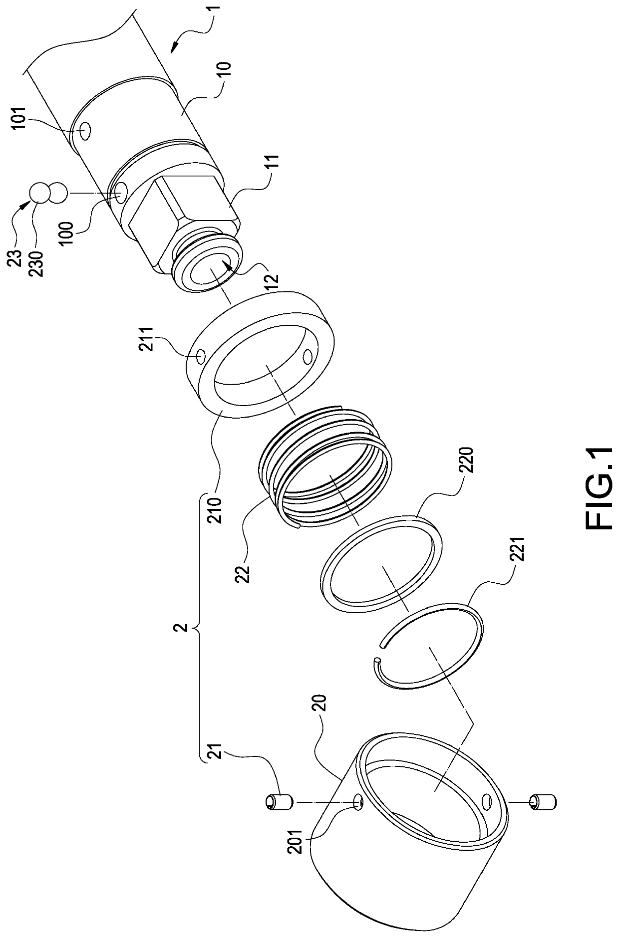
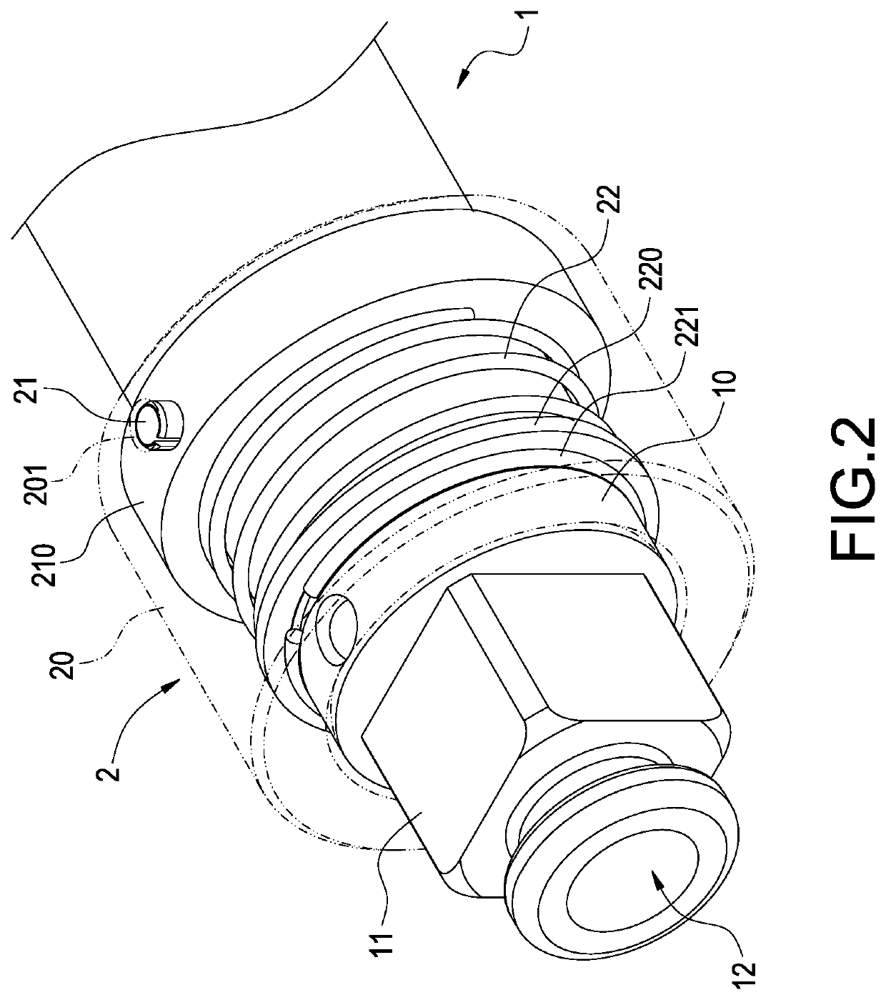
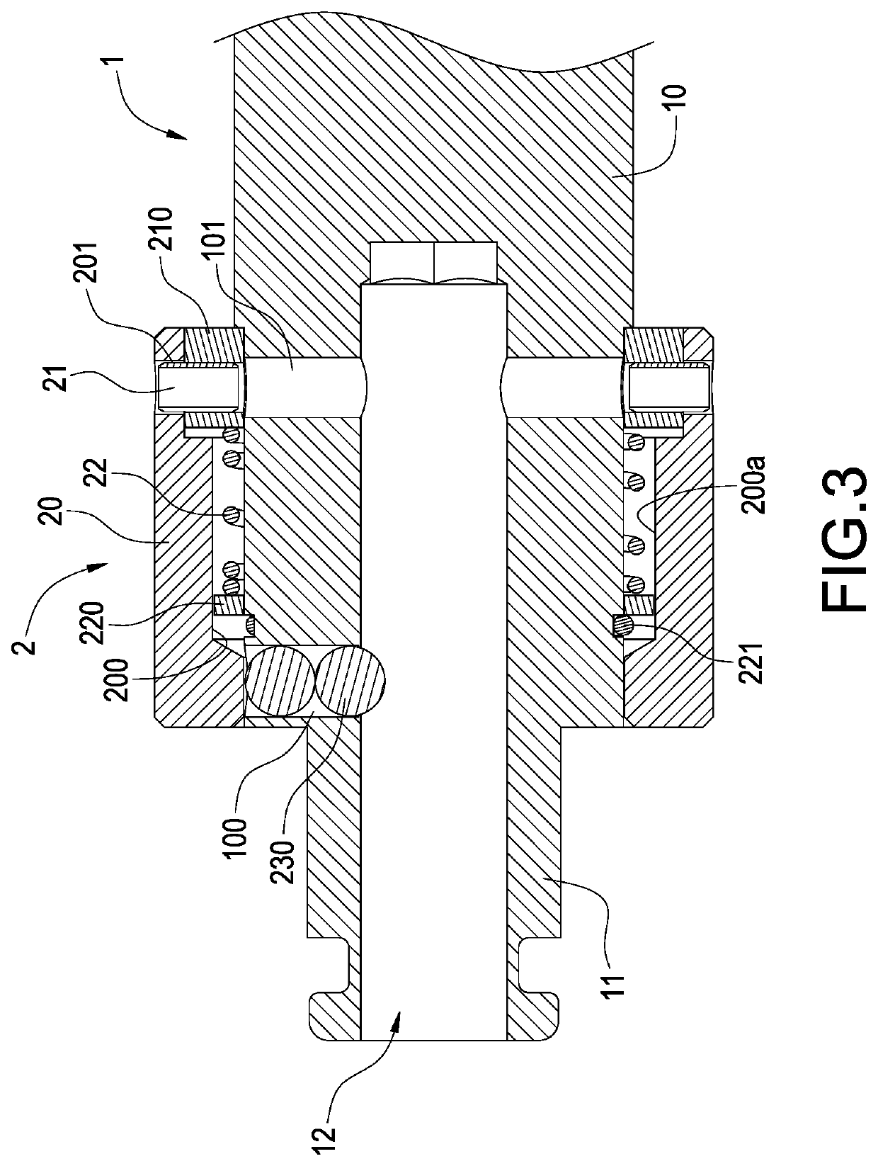
[0015]Please refer to FIG. 1, FIG. 2 and FIG. 3, showing an exploded perspective view, an assembly perspective view and an assembly cross sectional view of the present invention. The present invention provides a tool adapter quick-release structure, comprising an adapter 1 and a locking mechanism 2.

[0016]The adapter 1 is configured to be attached onto a handheld tool (not shown in the drawings) in order to facilitate the gripping and operation of a user. The adapter 1 includes a seat portion 10 and an engagement portion 11 extended forward from the seat portion 10, and an installation hole 12 formed to axially penetrate into an internal of the seat portion 10 via a front ...


PUM


Abstract

A tool adapter quick-release structure includes an adapter and a locking mechanism. The adapter includes a seat portion and an engagement portion extended forward from the seat portion, and an installation hole formed to penetrate into the seat portion via the engagement portion. The locking mechanism includes a movable sleeve mounted onto the seat portion, an installation pin inserted into the movable sleeve and an elastic member abutted against the installation pin to push the movable sleeve axially, and the movable sleeve allowing a fixation member to penetrate through the seat portion to protrude outward inside the installation hole via push of the elastic member. The seat portion includes a repair hole corresponding to the installation pin and is connected to the installation hole.

Description

BACKGROUND OF THE INVENTIONField of the Invention[0001]The technical field relates to a handheld tool, in particular, to a tool adapter quick-release structure for changing various types of screwdrivers.Description of Related Art[0002]Presently, regardless whether it is an electric or manual handheld tool, to facilitate the use of the tool in various situations along with the function of tool parts replacement, particularly to perform the actions of fastening or removal of flat head, cross head or hexagonal screws etc., it is necessary to use a corresponding screwdriver.[0003]However, in terms of the design, the output axle of a traditional handheld tool or power tool is typically not equipped with the function allowing users to perform removal, repair or replacement of parts individually. Consequently, after a long period of use of such tool, the internal components often require replacement and repair due to the problem of wear. For example, U.S. Pat. No. 9,566,696 discloses a han...

Claims


Application Information

Patent Timeline
Patent Type & Authority Patents(United States)
IPC IPC(8): B25B23/00B25B15/00
CPCB25B23/0035B25B15/001
Inventor HUA, CHIANGHUANG, FU-CHIANG
Owner BASSO IND CORP
Why Eureka
Try Eureka