Transmission-reflectance swappable Raman probe for physiological detections

a technology of raman probe and reflectance, which is applied in the field of measuring instruments, can solve the problems of large background noise, bulky and expensive, and each of the approaches has problems, and achieves the effect of facilitating the needs for accurate comparison, reducing noise generation, and reducing the loss of signal and noise generation of such equipmen

Active Publication Date: 2016-03-29
HONG KONG APPLIED SCI & TECH RES INST
View PDF18 Cites 1 Cited by
  • Summary
  • Abstract
  • Description
  • Claims
  • Application Information

AI Technical Summary

Benefits of technology

[0028]There are many advantages to the present invention. In particular, the present invention is advantageous over conventional approaches as mentioned previously. The present invention allows a quick switch between transmission mode and reflectance mode of operations with the same excitation light source, optical component and detector. It makes use of the same optical path for the signals travelling from the sample to the detector in both modes of operations. Such a device facilitates the needs for an accurate comparison between the transmission and reflectance signals. In many embodiments disclosed in this invention, mechanical component, i.e., a rotatable stage, is used to replace a number of optical components for switching between these two modes of operation while in other embodiments, the excitation light undergoes one or two more mirrors reflection when switching between these two modes. As such, the optical signal detection device disclosed herein can be constructed inexpensively and compactly. Since it requires only a minimum set of optical equipment for operation, signal loss and noise generation from such equipment will also be minimized.

Problems solved by technology

Each of these approaches has problems.
Its bulky and expensive.
Secondly, the system with additional optical components has additional background noise which is much larger than the blood signal we are going to detect.

Method used


Image

  • Transmission-reflectance swappable Raman probe for physiological detections
  • Transmission-reflectance swappable Raman probe for physiological detections
  • Transmission-reflectance swappable Raman probe for physiological detections

Examples


Embodiment Construction

[0044]The terminology used herein is for the purpose of describing particular embodiments and is not intended to be limiting of the inventive concepts. As used herein and in the claims, “comprising” means including the following elements but not excluding others.

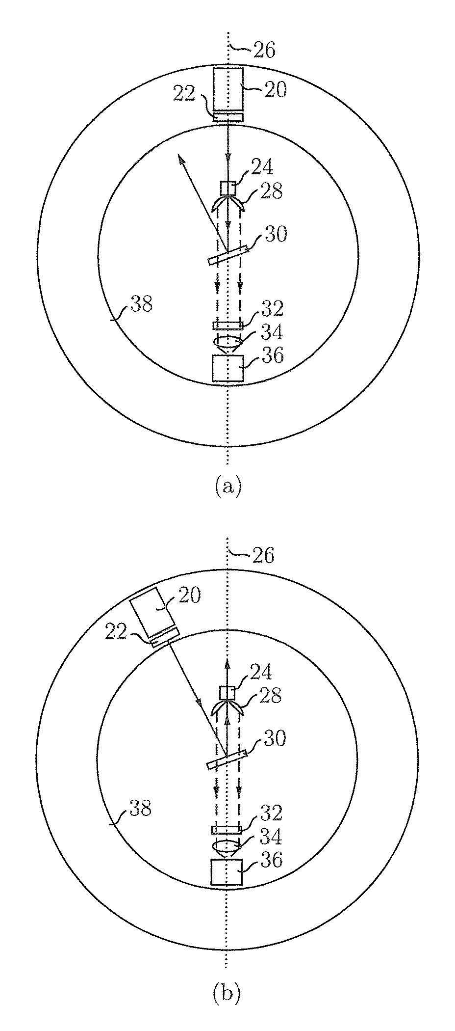
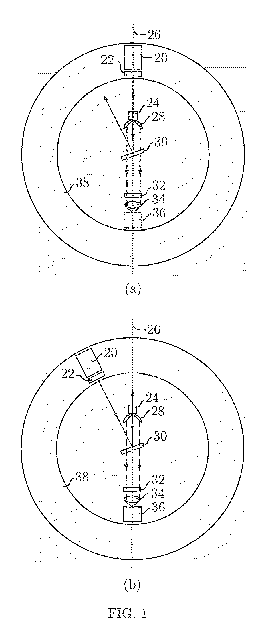
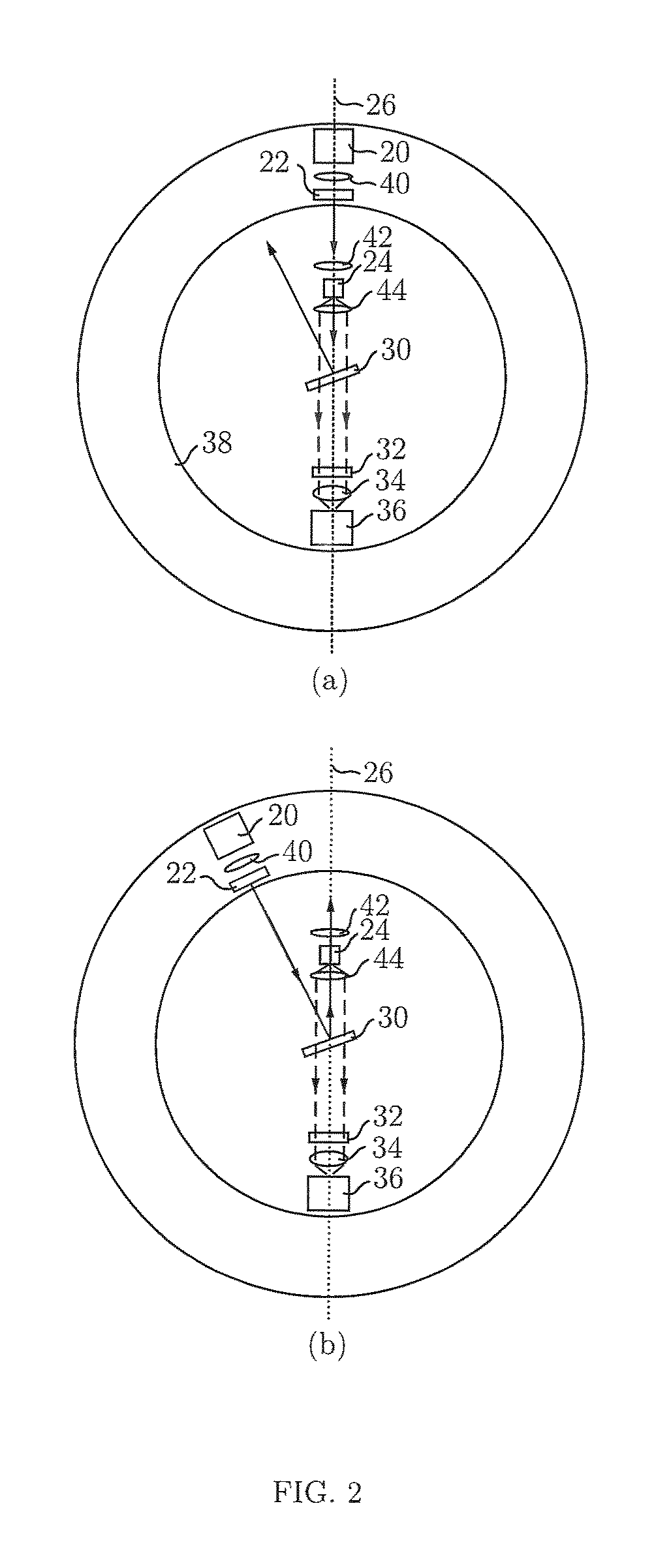
[0045]Referring to FIG. 1a and FIG. 1b, the transmission-reflectance swappable Raman probe according to one of the embodiments of the present invention includes a laser source 20, a sample holder 24 and a detector 36 coupled to a frame (coupling not shown for ease of illustration) along a signal axis 26. A line filter 22 is positioned in front of the laser source 20. A compound parabolic concentrator (CPC) 28, a first notch filter 30, a second notch filter 32 and a lens 34 are aligned respectively in this order between the sample holder 24 and the detector 36 along the signal axis 26, with the CPC 28 positioned closest to the sample holder 24 and the lens 34 positioned closest to the detector 36. The CPC 28 is configured wit...


PUM

PropertyMeasurementUnit
wavelengthaaaaaaaaaa
angleaaaaaaaaaa
FWHMaaaaaaaaaa

Abstract

A transmission-reflectance swappable Raman device and a method thereof are disclosed. The excitation light is selectively directed to the sample in one direction for generating the transmission Raman signal in transmission mode or in another direction for generating the reflectance Raman signal in reflectance mode. The content of an analyte in a sample can be determined by analyzing transmission and reflectance Raman signal.

Description

CROSS-REFERENCE TO RELATED APPLICATION[0001]This application claims benefit under 35 U.S.C. §119(e) of U.S. Provisional Application having Ser. No. 61 / 933,131 filed Jan. 29, 2014, which is hereby incorporated by reference herein in its entirety.FIELD OF INVENTION[0002]This invention relates to a measuring instrument and in particular a measuring instrument for detecting a content of an analyte in a sample by analyzing Raman signals obtained in transmission and reflectance modes.BACKGROUND OF INVENTION[0003]Noninvasive detection of a certain analytes in human blood, or noninvasive blood test, has been a dream for the last two decades. It is convenient, hygienic, and comfortable. One way to do this is to use optical means, namely, Raman spectroscopy.[0004]However, in such a noninvasive measurement, the Raman signal mainly arises from the skin and the spectral peaks corresponding to blood are not clear. While reflectance Raman signal is dominated by the response from the skin surface, ...

Claims


Application Information

Patent Timeline
Patent Type & Authority Patents(United States)
IPC IPC(8): G01J3/44G01N21/65G01N21/63A61B5/00A61B5/1455G01J3/02
CPCA61B5/1455A61B5/0075G01N21/63G01N21/65G01J3/0227G01J3/44G01N2201/06113G01J3/0202G01J3/0216G01J3/0237G01J3/06
Inventor ZHANG, CHUNKWOK, KA, CHEUNGLEUNG, LYDIA, LAP, WAI
Owner HONG KONG APPLIED SCI & TECH RES INST
Why Eureka
Try Eureka