Device for use in surgery

a retractor device and wound technology, applied in the field of surgical wound retractor devices, can solve the problems of requiring sterilisation, difficult and cumbersome use, and/or relatively expensive retractors,

Inactive Publication Date: 2002-01-03
ATROPOS LTD
View PDF0 Cites 219 Cited by
  • Summary
  • Abstract
  • Description
  • Claims
  • Application Information

AI Technical Summary

Problems solved by technology

However in general known retractors are difficult and cumbersome to use, and / or relatively expensive and / or require sterilisation.

Method used


Image

  • Device for use in surgery
  • Device for use in surgery
  • Device for use in surgery

Examples


Embodiment Construction

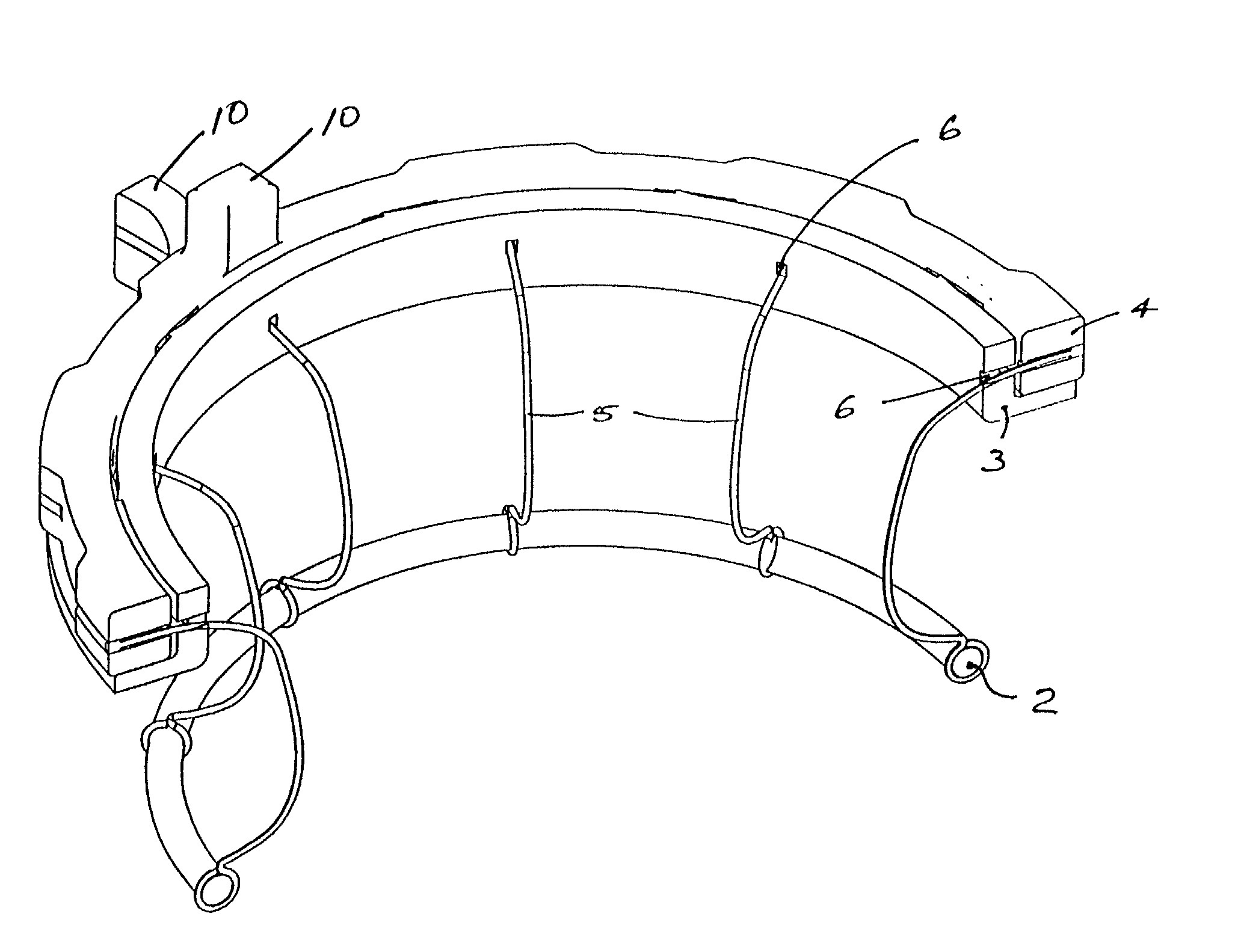
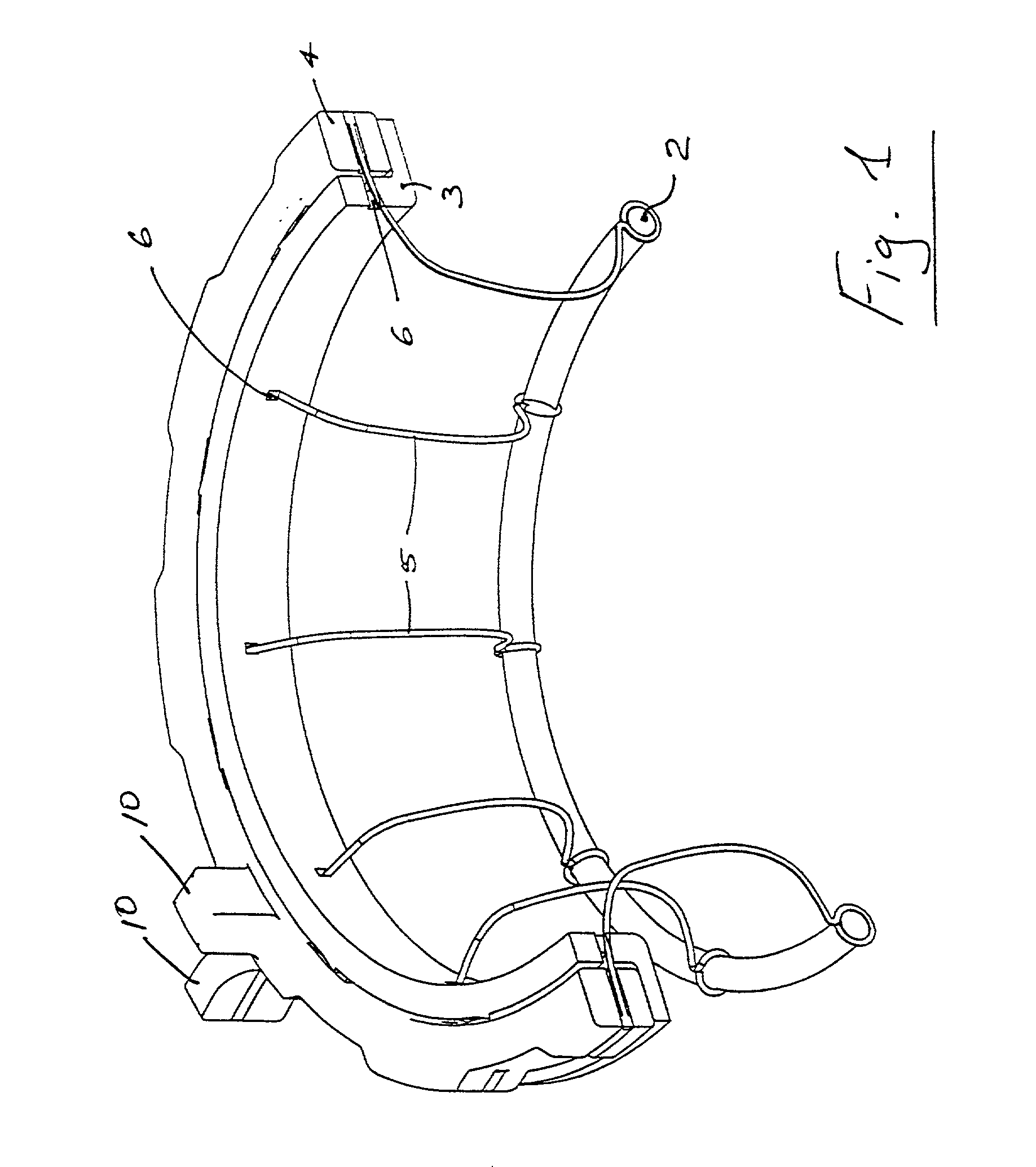
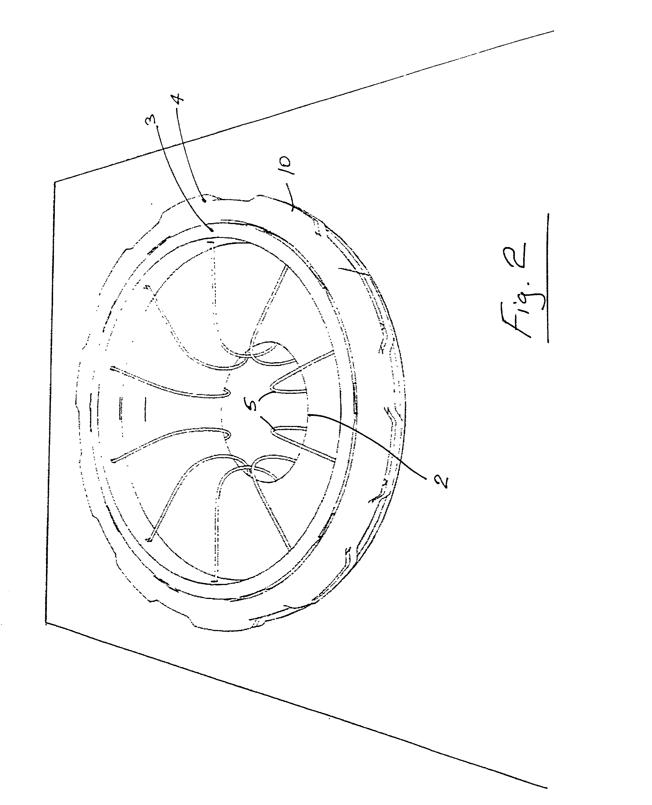
[0020] Referring to the drawings there is illustrated a wound retractor device 1 according to the invention. The device 1 consists of a thermoplastic inner O-ring 2 connected to an external ring assembly comprising an inner ring 3 and an outer ring 4 by a plurality of straps 5 of polymeric material. Each strap 5 passes through a guide hole 6 in the inner ring 3 of the external ring assembly to the outer ring 4 to which it is fixed. The rings 3, 4 are slidably rotatable relative to each other. Rotational movement of the outer ring 4 results in shortening of the distance between the external ring assembly and the internal ring 2 by taking up slack in the straps 5 and withdrawing it into the space between the rings 3, 4 of the external ring assembly, effectively shortening the length of and tensioning the straps 5.

[0021] The rings 3, 4 include formations 10 to assist in relative rotation of the rings. On tensioning of the straps 5 the rings 3, 4 may be locked by any suitable locking me...


PUM


Abstract

In one embodiment, a wound retractor includes a plurality of straps connected between an inner ring and an outer ring assembly. The inner ring is positioned internal of the wound so that it rests against the innermost tissue layer, and the outer ring is located outside of the wound adjacent the outermost tissue layer. The outer ring assembly includes an inner ring having guide holes for the passage of the straps and an outer ring to which the straps are affixed. Rotation of the outer ring of the outer ring assembly relative to the inner ring of the outer ring assembly results in a shorting of the effective length of the straps, retraction of the wound edge and exposure of the wound site.

Description

INTRODUCTION[0001] The invention relates to a surgical wound retractor device.[0002] Various retractors are known. However in general known retractors are difficult and cumbersome to use, and / or relatively expensive and / or require sterilisation. This invention is direct towards providing an improved wound retractor which will over come at least some of these problems.STATEMENTS OF INVENTION[0003] According to the invention there is provided a surgical wound retractor comprising:an[0004] an inner mounting means for insertion into a wound opening to be retained inside the wound opening;[0005] an outer retracting means;[0006] connecting means between the inner mounting means and the outer retracting means;[0007] the outer retracting means being operable to pull the connecting means laterally to retract the wound opening.[0008] In one embodiment of the invention the connecting means comprises a plurality of spaced-apart straps extending between the inner mounting means and the outer ret...

Claims


Application Information

Patent Timeline
Patent Type & Authority Applications(United States)
IPC IPC(8): A61B17/02A61B17/34
CPCA61B17/0293A61B17/3423
Inventor MCMANUS, RONAN BERNARD
Owner ATROPOS LTD
Why Eureka
Try Eureka