

Workpiece handling device
a technology for handling devices and workpieces, which is applied in the direction of stacking articles, packaging goods types, manufacturing tools, etc., can solve the problems that the workpiece bundling devices and the workpiece posture changing devices that have been proposed have not provided users with satisfaction
- Summary
- Abstract
- Description
- Claims
- Application Information
AI Technical Summary
Benefits of technology
Problems solved by technology
Method used
Image

Examples
first embodiment
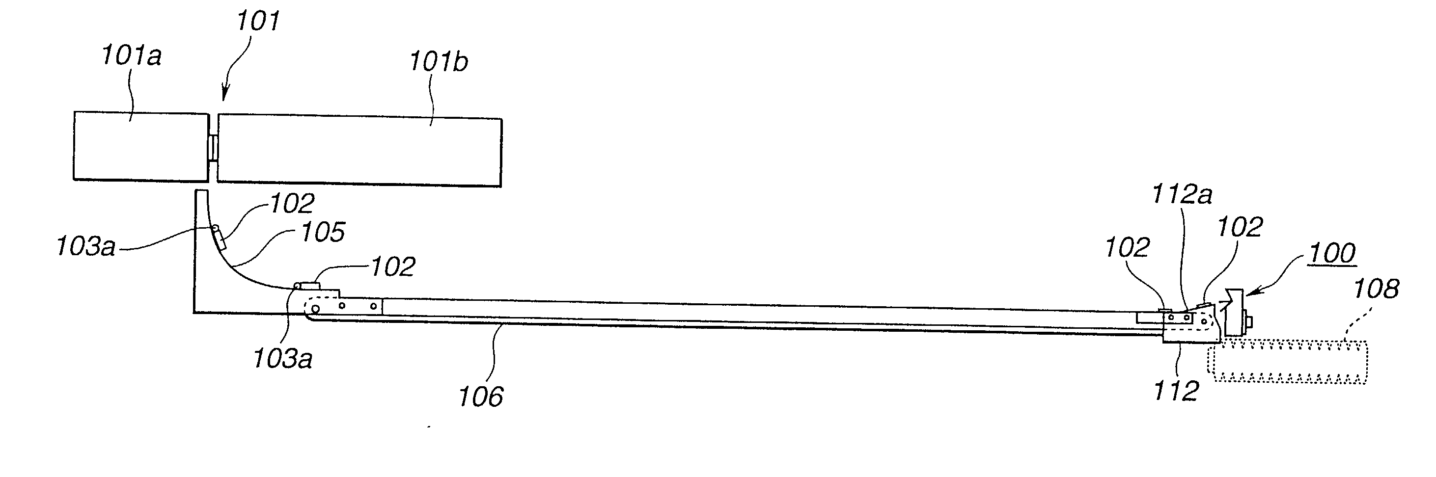
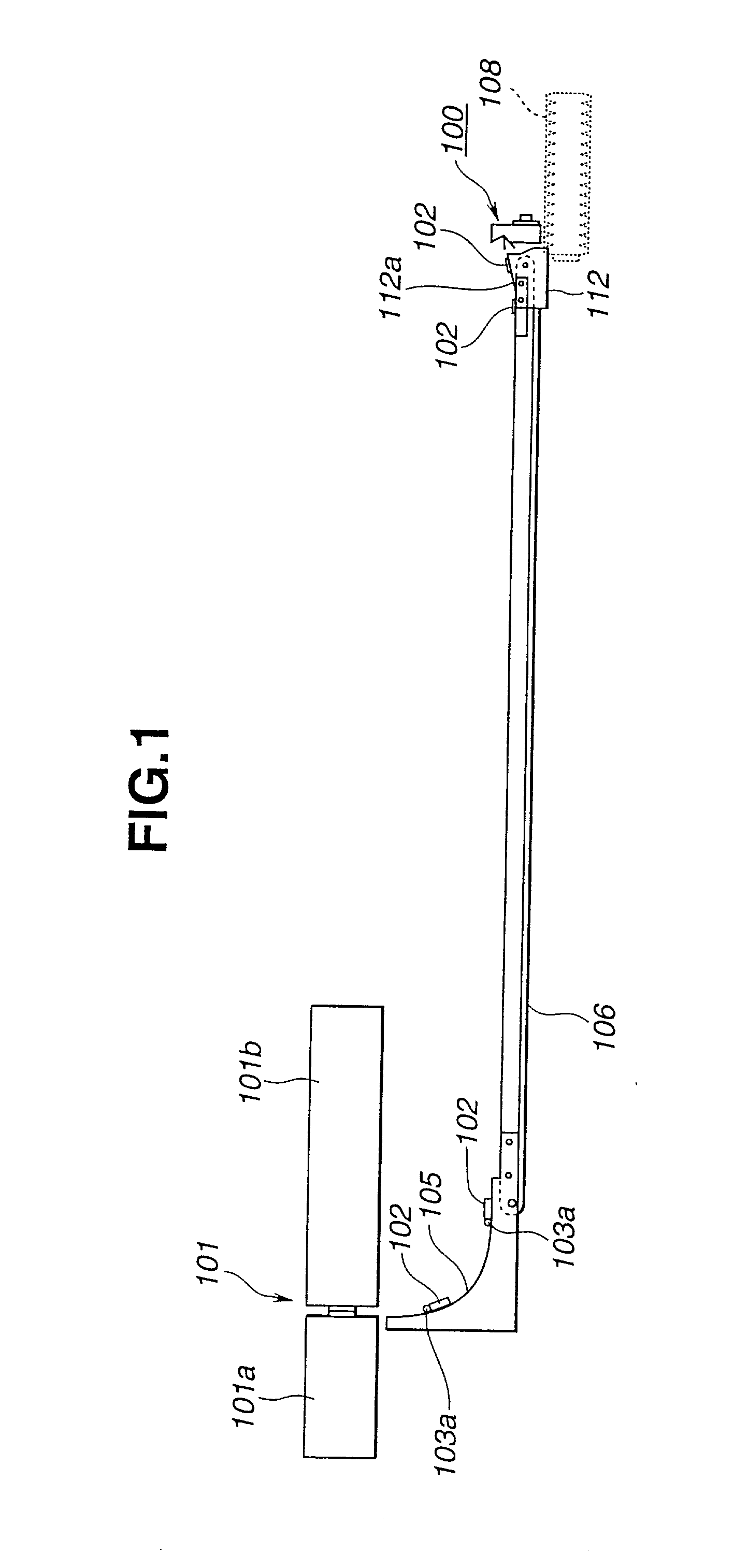
[0027] Referring to FIGS. 1 to 4B, particularly FIG. 1, there is shown a workpiece posture changing device 100 of the present invention, which is arranged in a manufacturing line of producing a condenser of an automotive air conditioner.
[0028] In FIG. 1, denoted by numeral 101 is a press machine for continuously producing flat tubes 102 used as essential elements of a core unit of the condenser. The flat tube 102 is shown in FIG. 4. As shown in FIG. 1, the press machine 101 comprises a fixed die 101a and a movable die 101b.
[0029] For producing the flat tube 102 by the press machine 101, the following production steps are carried out. That is, as is seen from FIGS. 1 and 4, a flat and elongate aluminum plate 103 is horizontally oriented and put between the two dies 101a and 101b, and the movable die 101b is moved toward the fixed die 101a and then moved away from the fixed die 101a. With this, as is seen from FIG. 4A, the plate 103 is bent at its vertically middle portion 103b to for...
second embodiment
[0041] Referring to FIGS. FIGS. 5 to 15, particularly FIGS. 5 to 7, there is shown a workpiece bundling device 200 which is the present invention. It is to be noted that the workpiece bundling device 200 is positioned just downstream of the above-mentioned workpiece posture changing device 100.
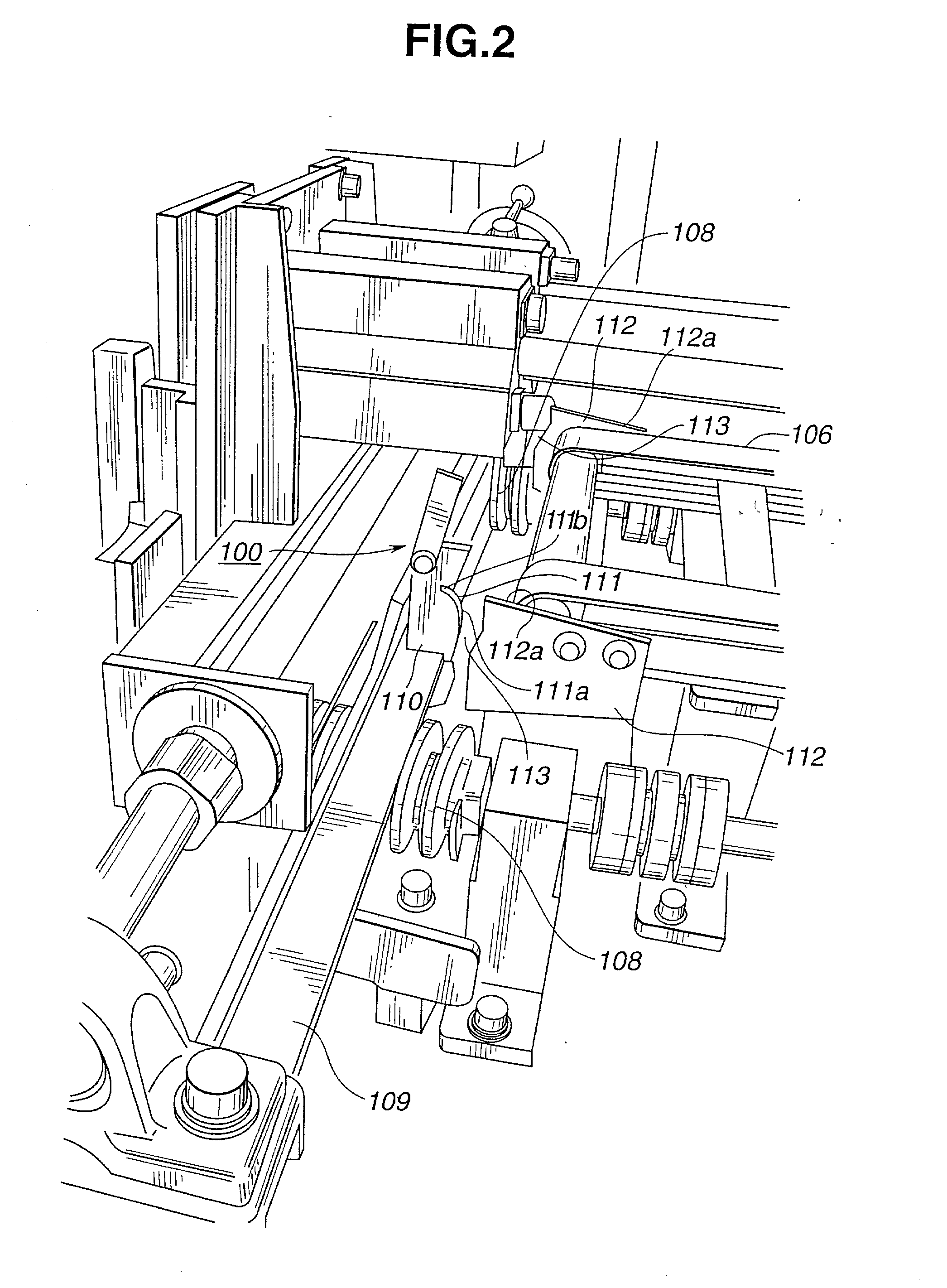
[0042] As is best seen from FIG. 7, the workpiece bundling device 200 comprises a base stand 1 which is constructed of frame members. Two rectangular flat tables 2 and 2 are horizontally arranged on the base stand 1 keeping a certain distance therebetween. The tables 2 and 2 have at their rear ends respective rectangular cuts (no numeral) to which downstream ends of the above-mentioned screw rods 108 are exposed. The two screw rods 108 and 108 constitute the screw conveyer 108 (see FIG. 2) by which flat tubes 102 are conveyed to the tables 2 and 2 from the upstream end of the screw conveyer 108. As has been mentioned in the section of the first embodiment 100, during the conveyance of the flat...
PUM
| Property | Measurement | Unit |
|---|---|---|
| mass | aaaaa | aaaaa |
| movement | aaaaa | aaaaa |
| force | aaaaa | aaaaa |
Abstract
Description
Claims
Application Information