
Relaying apparatus

Inactive Publication Date: 2002-05-23
FUJITSU LTD
View PDF9 Cites 84 Cited by
  • Summary
  • Abstract
  • Description
  • Claims
  • Application Information

AI Technical Summary

Problems solved by technology

Namely, there is a problem that the bandwidth in the output from the input side accommodating portion 10 to the switch fabric 40 can not be efficiently used.
However, there is a problem that it is necessary for all of the input side accommodating portions 10 to transmit the various kinds of packet information to the switch fabric 40, so that the scheduling of the switch fabric 40 becomes complicated, the hardware scale becomes large, and the cost increases.
Accordingly, this method can not be applied to the (connectionless) packet which does not set up the connection before the data transmission.
Namely, as for such a packet, it is impossible to anticipate its existence and arrival, so that the bandwidth can not be preferentially reserved.
Accordingly, since the number of the queues to be controlled as well as the calculation amount of the packet output schedule time and the like increase, there is a problem that it becomes difficult to secure the process rate corresponding to the rate of the physical link 62 by the applied scheduling algorithm.

Method used


Image

  • Relaying apparatus
  • Relaying apparatus
  • Relaying apparatus

Examples


Embodiment Construction

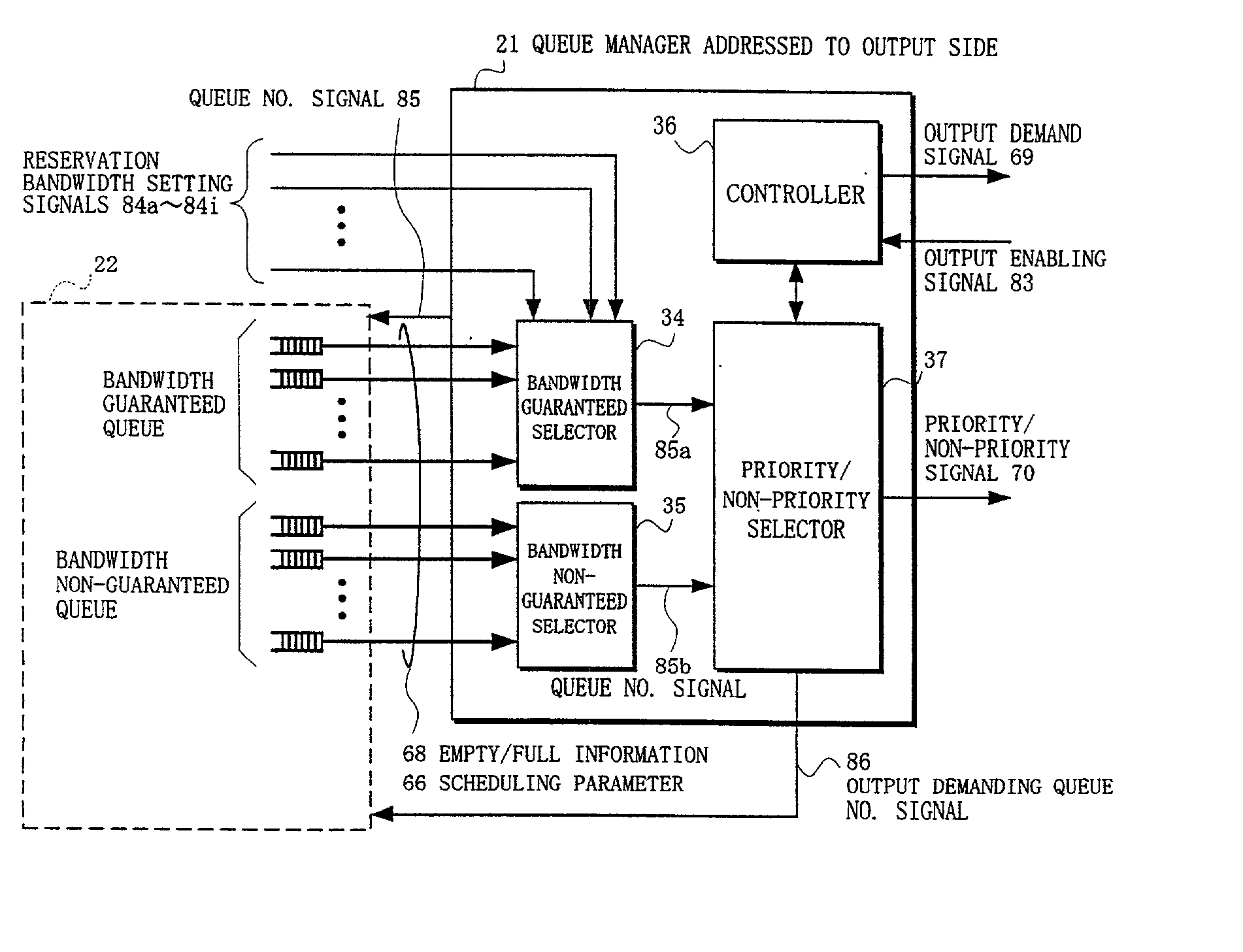
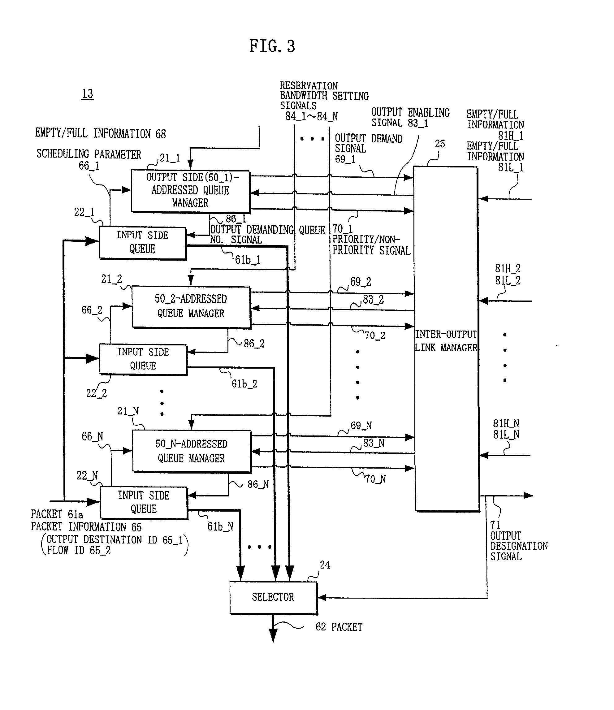
[0116] The basic arrangement of the relaying apparatus according to the present invention is the same as that of the general relaying apparatus shown in FIG. 10, whereas the operation of the input side scheduler 13 (see FIGS. 3 and 11) included in the input side accommodating portions 10_1-10_N is different from that of the prior art input side scheduler 13. Priority queues and non-priority queue are arranged, as will be described later, in the output side accommodating portions 50_1-50_N.

[0117] It is to be noted that the numbers of the input side accommodating portions 10 and the output side accommodating portions 50 are assumed to be the same "N" in FIG. 10, while those numbers may be different from each other.

[0118] Although the output side queue can also be arranged at the switch fabric 40, it is assumed to be arranged at the input side of the output side accommodating portion 50 and to be included in the output side accommodating portion 50. Also, the queue selection algorithm ...


PUM


Abstract

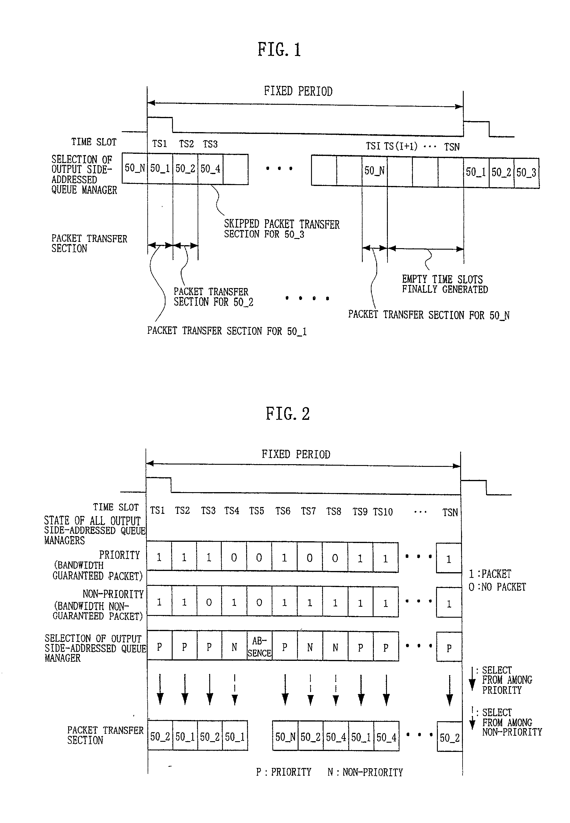
In a relaying apparatus comprising input side accommodating portions including input side queues, a plurality of output side accommodating portions including output side queues, and a switch fabric for mutually connecting the input side queues and the output side queues in a mesh form, in a time slot of a fixed period, the output side-addressed queue managers corresponding to the output side accommodating portions select a bandwidth guaranteed packet so as to guarantee a bandwidth, and output priority / non-priority signals for indicating which of the bandwidth guaranteed packet and a bandwidth non-guaranteed packet has been selected, and output demand signals of the packet. An inter-output link manager selects the packet having an empty area in the priority queue or non-priority queue of the output side accommodating portion as a destination corresponding to the packet which is demanded to be outputted.

Description

[0001] 1. Field of the Invention[0002] The present invention relates to a relaying apparatus, and in particular to a relaying apparatus comprising input side accommodating portions including input side queues, a plurality of output side accommodating portions respectively including output side queues, and a switch fabric for mutually connecting the input side queues and the output side queues in a mesh form.[0003] A relaying apparatus such as a router accommodating a plurality of networks and relaying packets between the networks receives the packet from the input side network, determines the output side network for the packet, and performs routing for the transmission of the packet to the determined network.[0004] In such a relaying apparatus, it is possible that the packets are simultaneously transmitted to a single output side network from a plurality of input side networks. Thus, the issue of the competition of scrambling for the output side network occurs. This issue can be sol...

Claims


Application Information

Patent Timeline
IPC IPC(8): H04J3/16H04L47/22H04L47/52H04L47/6275H04L69/14
CPCH04J3/1682H04L12/5693H04L47/6215H04L47/60H04L47/522H04L47/50
Inventor ABIRU, KENICHIAMOU, KENSAKUXU, YAN
Owner FUJITSU LTD
Learn More