Ink jet printer head
a printer head and jet printer technology, applied in printing and other directions, can solve the problems of inability to concentrate the nozzle columns for ejecting ink, inability to obtain predetermined ink ejection, and shortening the service life of the nozzle column,
- Summary
- Abstract
- Description
- Claims
- Application Information
AI Technical Summary
Problems solved by technology
Method used
Image
Examples
first embodiment
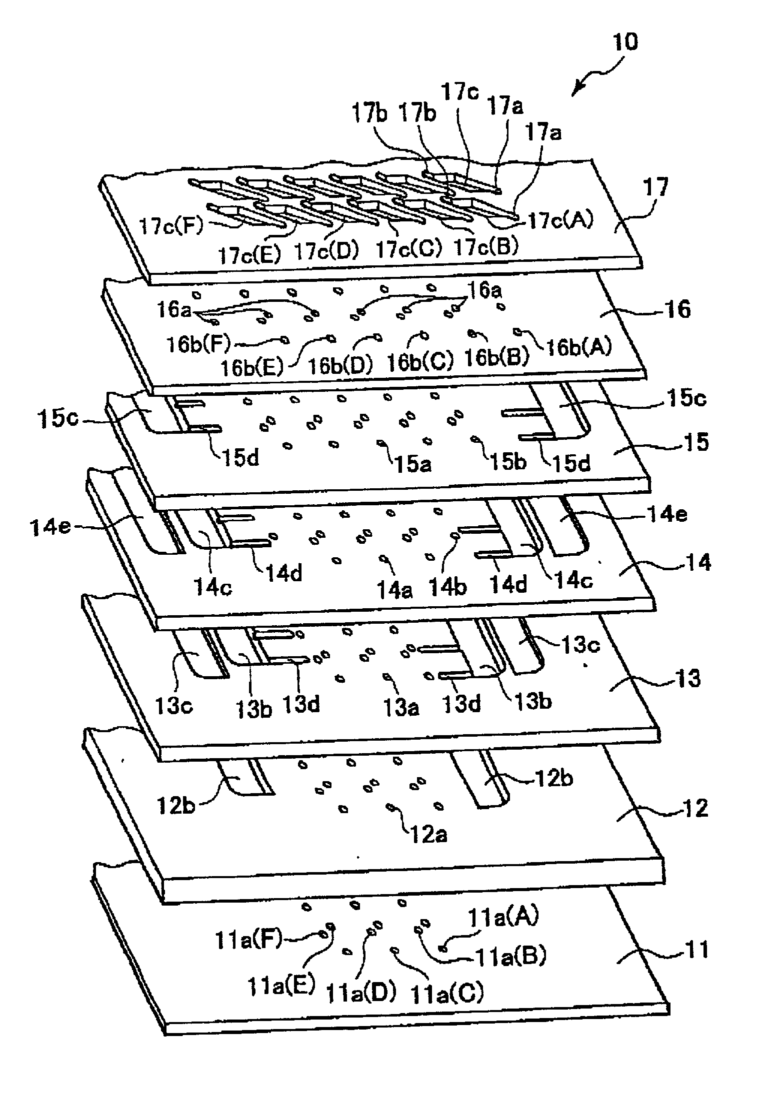
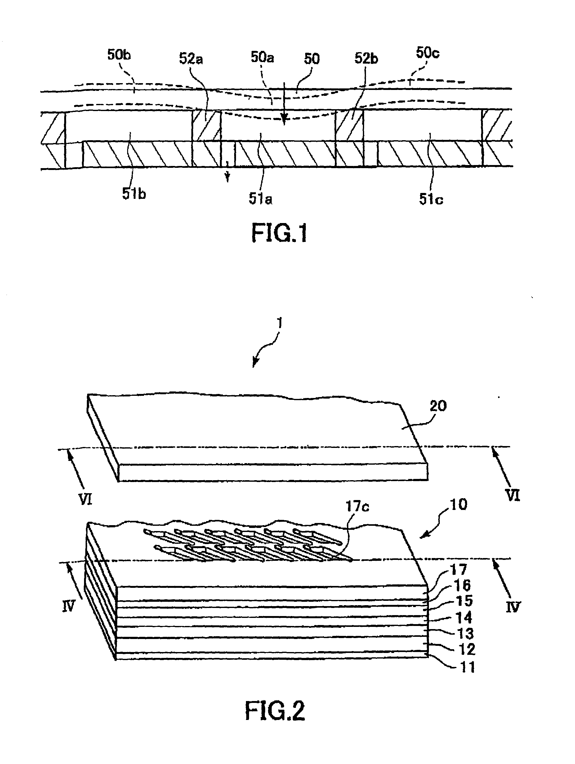
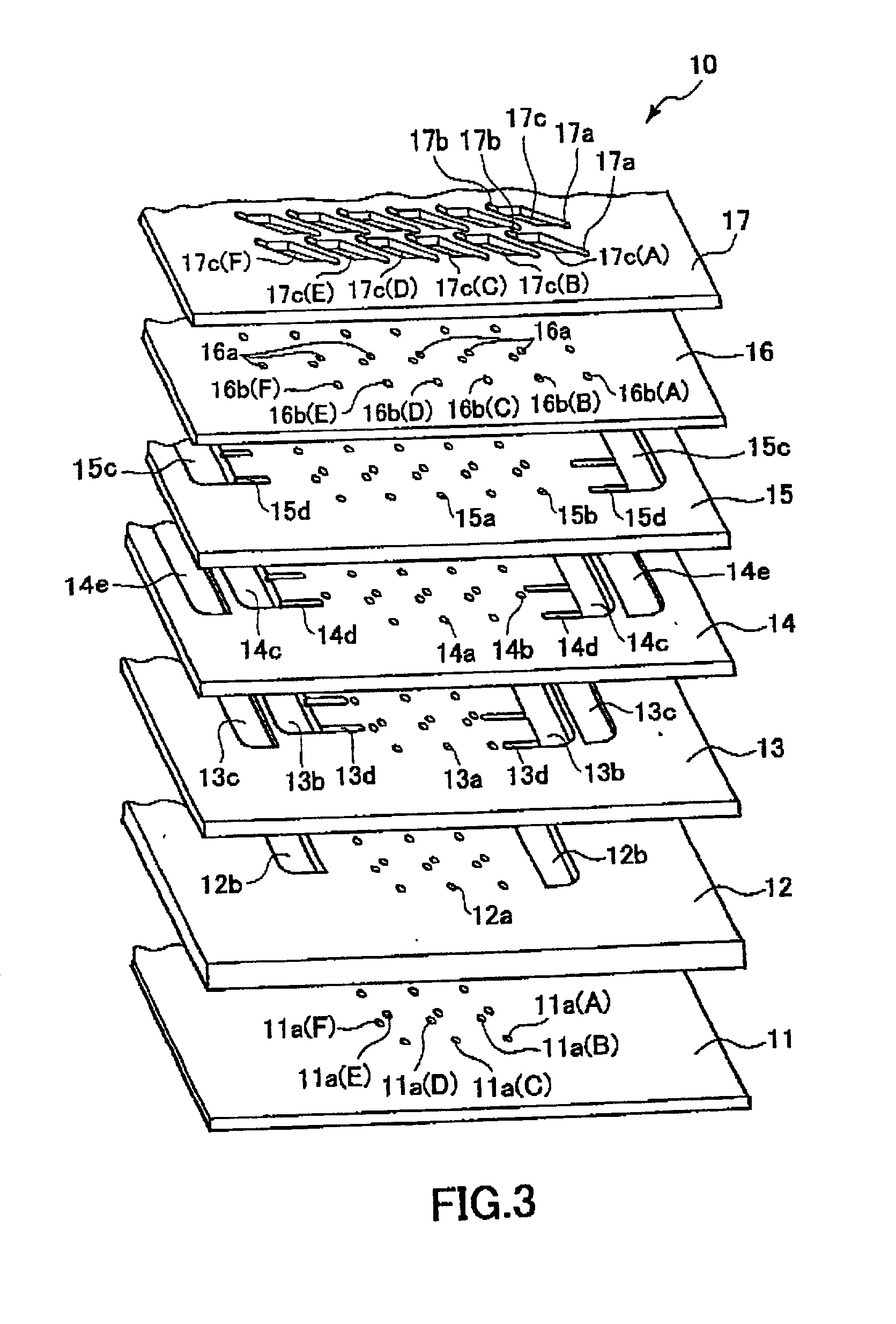
[0040] First, an ink jet printer head 1 will be described while referring to FIGS. 2 to 9. As shown in FIG. 2, the ink jet printer head 1 includes a cavity plate 10 and a plate-shaped piezoelectric actuator 20. The cavity plate 10 is configured from laminated metal plates each having a rectangular shape. The actuator 20 is stacked on top of the cavity plate 10. The surface of the cavity plate 10 is formed with plural columns of ink pressure chambers 17c. Each ink pressure chamber 17c has a substantial parallelogram shape with two acute and two obtuse angled portions. This configuration enables providing a plurality of ink pressure chambers without increasing the size of the cavity plate 10.
[0041] Next, the configuration of the cavity plate 10 will be described while referring to FIGS. 3 and 4. As shown in FIGS. 3 and 4, the cavity plate 10 has a seven-layer configuration made from seven thin layers of rectangular metal plates. The seven layers are, from the bottom up, a nozzle plat...
second embodiment
[0083] The actuator unit deforms most into (or away from) the pressure chambers at the principal portions. If the principal portions of an adjacent pressure chamber were aligned in the direction perpendicular to one of the lines a, which is the direction of extension of the perpendicular lines f, f, then as explained with reference to FIG. 1 the deformation of the actuator into (or away from) one of the pressure chambers would also influence adjacent pressure chambers. However, with the configuration of the second embodiment, the portion of the actuator unit that is located at the principal portion of a pressure chamber in one column confronts, that is, in a direction that extends perpendicular to one of the lines a of the pressure chamber, portions of the actuator unit located 1) where the actuator unit is securely fixed to a partition wall 112 that is sandwiched between short lines b, b, of two pressure chambers 111 in an adjacent column and 2) where one of the acute-angle portion...
PUM
 Abstract
Description
Claims
Application Information
 - R&D
- Intellectual Property
- Life Sciences
- Materials
- Tech Scout
- Unparalleled Data Quality
- Higher Quality Content
- 60% Fewer Hallucinations
Browse by: Latest US Patents, China's latest patents, Technical Efficacy Thesaurus, Application Domain, Technology Topic, Popular Technical Reports.
© 2025 PatSnap. All rights reserved.Legal|Privacy policy|Modern Slavery Act Transparency Statement|Sitemap|About US| Contact US: help@patsnap.com


