
Initiating device for an electronic detonator

Inactive Publication Date: 2002-07-25
ORICA EXPLOSIVES TECH PTY LTD
View PDF0 Cites 13 Cited by
  • Summary
  • Abstract
  • Description
  • Claims
  • Application Information

AI Technical Summary

Benefits of technology

[0010] It is accordingly an object of the present invention to provide an initiating device for an electronic detonator with which the aforesaid disadvantages may be overcome or at least minimised.

Problems solved by technology

A disadvantage of initiating devices known in the art, and particularly those referred to above, is that the reliability of these devices is limited due to the application of a single resistive element.
Should the element fail, the entire initiating device fails as a result.
Another disadvantage of such initiating devices is that the contact interface between the resistive element and the explosives composition is limited to the size of the surface of the element in contact with the explosives or pyrotechnic composition.
As electronic integrated circuits of the type used in electronic detonators and other electronically controlled initiators, become relatively smaller through progress of technology, their potential current consumption diminishes accordingly.
Initiating devices, which operate at elevated energy levels, are therefor undesirable in these applications.

Method used


Image

  • Initiating device for an electronic detonator
  • Initiating device for an electronic detonator
  • Initiating device for an electronic detonator

Examples


Embodiment Construction

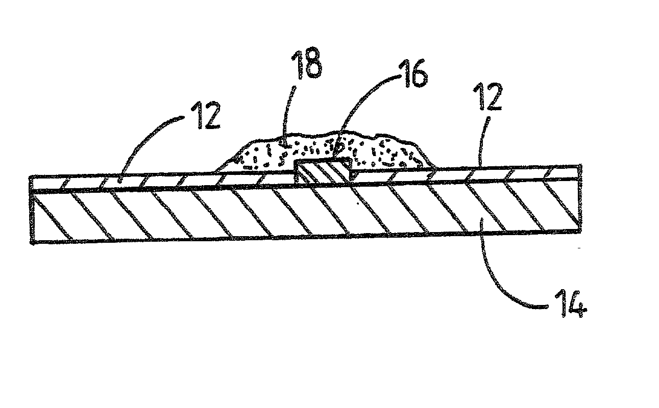
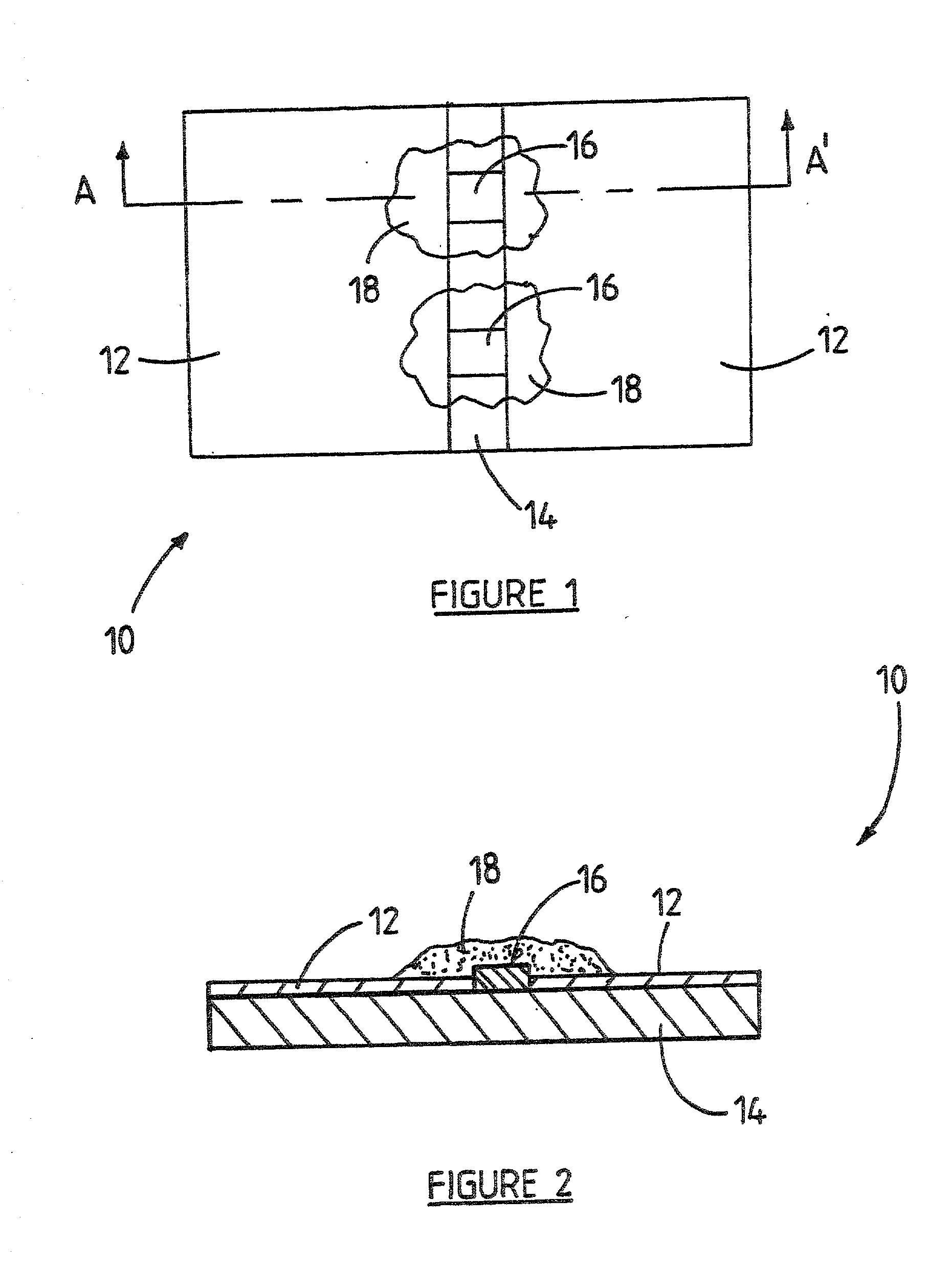
[0030] Referring to FIGS. 1 and 2, according to a first embodiment, the initiating device 10 includes two spaced electrical conductors 12 located on an insulating substrate 14; and two separate resistive means in the form of thick film resistive bridges 16 extending between the electrical conductors 12, for releasing energy upon application of an electrical current to the resistive bridges 16.

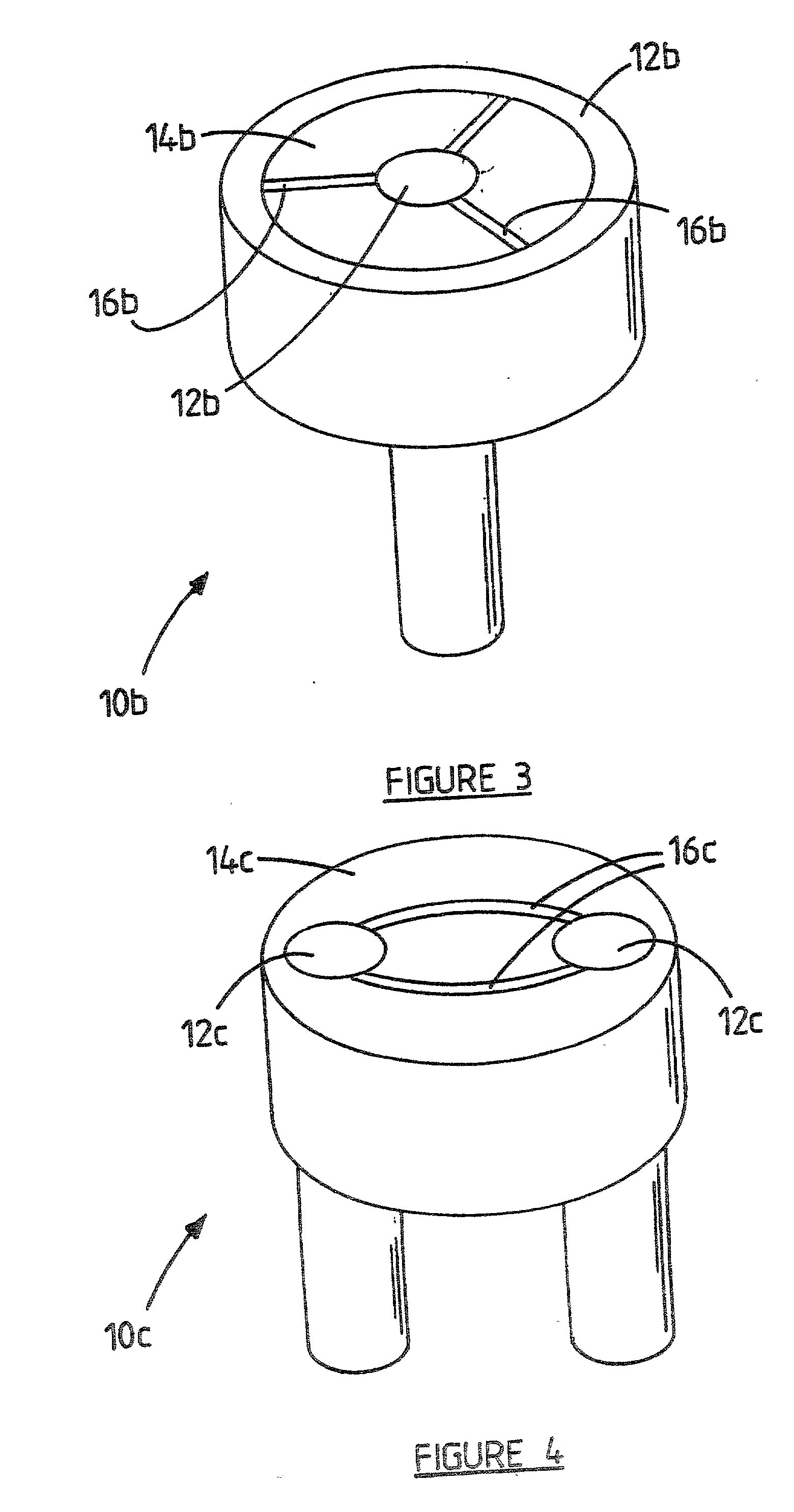
[0031] An explosives or pyrotechnic composition, generally designated by reference numeral 18, covers the resistive bridges 16. It will be appreciated that the resistive means need not necessarily be in the form of thick film bridges, but could also be in the form of thin film bridges, wires, dope substances or other resistive substances. There could also be no physical bridge present at all, in which case the resistive path being created by the conductive explosive or pyrotechnic composition itself (see FIGS. 5 and 6).

[0032] The energy requirement of single path resistive initiation devices is...


PUM


Abstract

This invention provides an initiating device 10 for an electronic detonator, which includes two spaced electrical conductors 12 located on an insulating substrate 14; and two separate resistive means in the form of thick film resistive bridges 16 extending between the electrical conductors 12, for releasing energy upon application of an electrical current to the resistive bridges 16. An explosives or pyrotechnic composition, generally designated by reference numeral 18, covers the resistive bridges 16. It will be appreciated that should one of the bridges 16 fail, the other bridge 16 would still initiate the device 10. The size of the contact interface between the bridge 16 and the explosives composition 18 is also doubled, making the initiating device 10 even more reliable. As a result the initiating device 10 is suitable for a wide range of different applications.

Description

INTRODUCTION AND BACKGROUND TO THE INVENTION[0001] This invention relates to an initiating device. More particularly but not exclusively this invention relates to a novel initiating device suitable for use with electronic detonators.[0002] All known resistive initiating devices include a single resistive element that is connected by some or other means to, or is in close contact with, electrically conductive areas and / or current feed mechanisms so as to provide the necessary connection to the energy source required to cause ignition on functioning.[0003] For example, a known detonator initiating device comprises two spaced electrical conductors; and a resistive element extending between the electrical conductors, for releasing energy upon application of an electrical current to the element. The resistive element is embedded in an explosives or pyrotechnic composition, which, in use, is ignited by the resistive element.[0004] Further for example, U.S. Pat. Nos. 2,960,933; 3,763,782; ...

Claims


Application Information

Patent Timeline
IPC IPC(8): F42B3/12
CPCF42B3/124
Inventor GOOSEN, ADRIAAN J.MEYER, ERICH N.
Owner ORICA EXPLOSIVES TECH PTY LTD
Learn More