Anti-roll bar with link actuator for controlling torsional rigitidy

a technology of torsional rigitidy and anti-roll bar, which is applied in the direction of mechanical equipment, shock absorbers, transportation and packaging, etc., can solve the problems of many parts of the known system, the intermediate portion of the anti-roll bar may be subjected to a torsional force, and the vehicle ride may be affected

Inactive Publication Date: 2002-08-22
TRW INC
View PDF0 Cites 50 Cited by
  • Summary
  • Abstract
  • Description
  • Claims
  • Application Information

AI Technical Summary

Benefits of technology

The invention is a device used in a vehicle's suspension system. It consists of an anti-roll bar that is attached to the suspension system using a special actuator. The actuator has a cylinder and a piston assembly with adjustable orifices that control the resistance to movement of the anti-roll bar. The technical effect of this invention is to improve the stability and control of the vehicle's suspension system, especially in situations where the vehicle is being driven on uneven surfaces.

Problems solved by technology

The technical problem addressed in this patent text is to provide an improved anti-roll bar system for vehicles that is simpler and more efficient than existing systems.

Method used


Image

  • Anti-roll bar with link actuator for controlling torsional rigitidy
  • Anti-roll bar with link actuator for controlling torsional rigitidy
  • Anti-roll bar with link actuator for controlling torsional rigitidy

Examples


Embodiment Construction

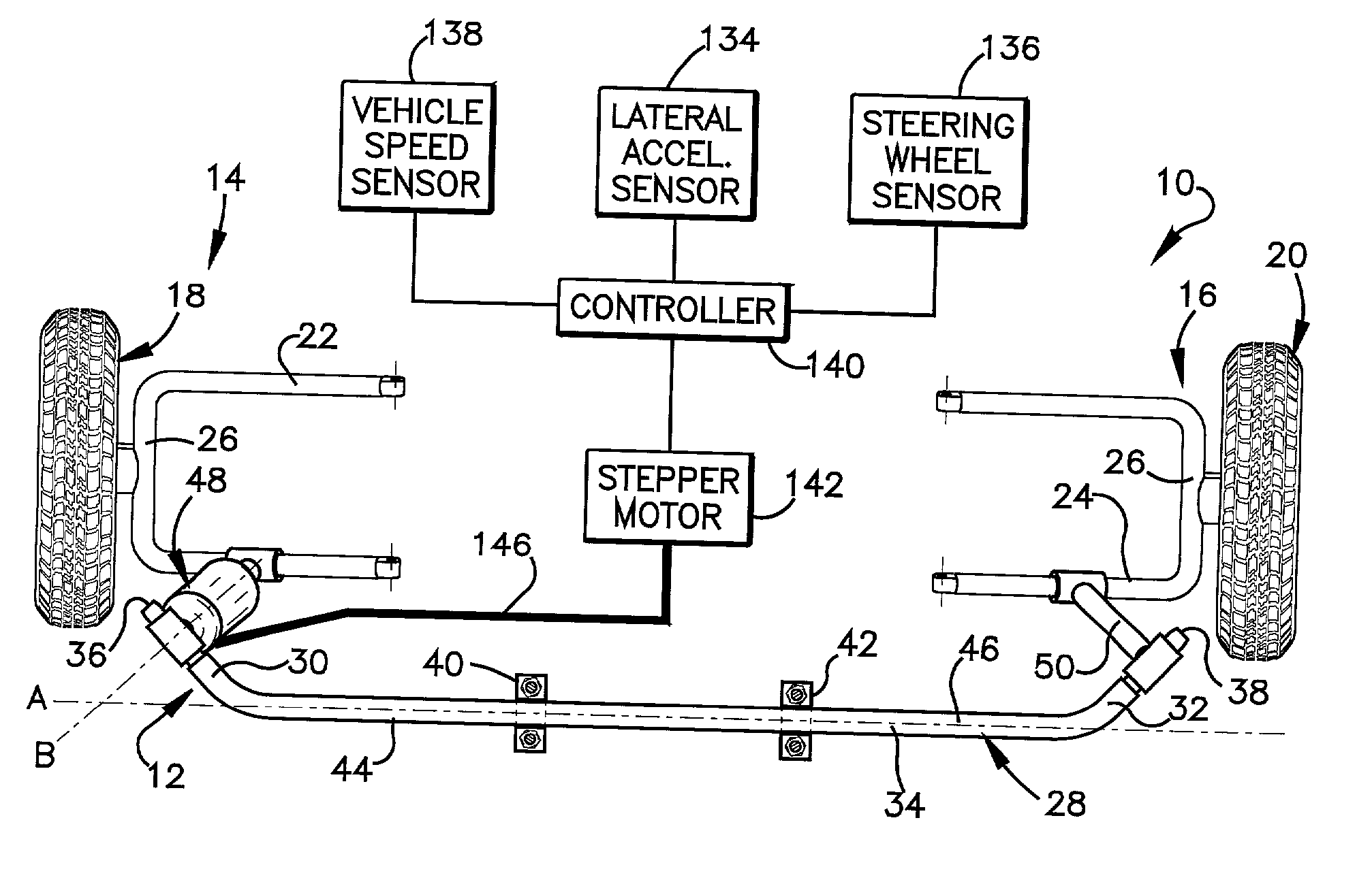
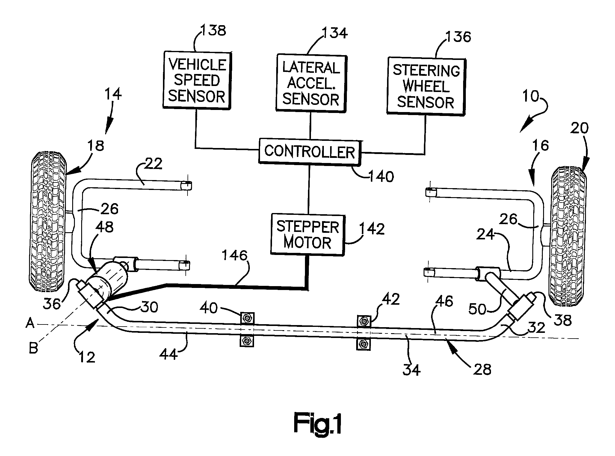
[0015] FIG. 1 schematically illustrates a portion of a vehicle suspension 10 including an apparatus 12 of the present invention.

[0016] The suspension 10 includes a left-hand side 14 and a right-hand side 16. A first steerable wheel 18 is connected to the left-hand side 14 of the suspension 10 and a second steerable wheel 20 is connected to the right-hand side 16 of the suspension 10.

[0017] The left-hand side 14 of the suspension 10 includes a first control arm 22 and the right-hand side 16 of the suspension 10 includes a second control arm 24. Both the first and second control arms 22 and 24 are U-shaped. Steerable wheel 18 connects with a closed portion 26 of the U-shape of control arm 22. Steerable wheel 20 connects with a closed portion 27 of the U-shape of control arm 24.

[0018] The apparatus 12 of the present invention includes an anti-roll bar 28. The anti-roll bar 28 includes opposite first and second end portions 30 and 32, respectively. An intermediate portion 34 is interpos...


PUM


Abstract

An apparatus (12) for use in a vehicle suspension (10) comprises an anti-roll bar (28) having opposite first and second end portions (30 and 32). An intermediate portion (34) is interposed between the first and second end portions (30 and 32) and is subjected to torsional forces when the first and second end portions (30 and 32) move relative to one another. The apparatus (12) further comprises an actuator (48) for attaching at least one of the first and second end portions (30 and 32) to a part of the vehicle suspension (10). The actuator (48) comprises a cylinder (52) for retaining fluid (54) and a piston assembly (56) for dividing the cylinder into two chambers (81 and 83). The piston assembly (56) is movable axially within the cylinder (52). The piston assembly (56) includes structure forming orifices (144) for interconnecting the two chambers (81 and 83) of the cylinder (52). A fluid flow area of the orifices (144) is adjustable to vary a resistance to relative movement of the first and second end portions (30 and 32) of the anti-roll bar (28).

Description


Claims


Application Information

Patent Timeline
Owner TRW INC
Why Eureka
Try Eureka