Anti-roll bar and control arm assembly

a control arm and anti-roll bar technology, applied in the direction of interconnection systems, resilient suspensions, vehicle springs, etc., can solve the problems of increasing the overall packaging size of the vehicle suspension, increasing the cost and time consumption of two different types of connection interfaces for the anti-roll bar, and reducing ground clearance, so as to achieve the effect of improving ground clearan

Inactive Publication Date: 2009-06-02
ARVINMERITOR TECH
View PDF20 Cites 8 Cited by
  • Summary
  • Abstract
  • Description
  • Claims
  • Application Information

AI Technical Summary

Benefits of technology

[0007]An anti-roll bar is attached to first and second control arms in a vehicle suspension. The anti-roll bar is positioned within an envelope of space defined by the first and second control arms such that the anti-roll bar does not extend longitudinally beyond distal ends of the first and second control arms, and does not extend vertically below lower surfaces of the first and second control arms. This configuration allows the vehicle suspension to be packaged within a smaller space, and improves ground clearance.
[0010]This configuration provides a compact suspension design with improved ground clearance. Further, the “bolt-on” design allows different anti-roll bars to be installed within a common vehicle suspension. Thus, anti-roll bars with different strengths or stiffnesses can be provided to “tune” the vehicle suspension to perform as needed for different applications.

Problems solved by technology

Having two different types of connection interfaces for the anti-roll bar is expensive and time consuming from an assembly standpoint.
This increases the overall packaging size for the vehicle suspension and reduces ground clearance, both of which are undesirable.

Method used


Image

  • Anti-roll bar and control arm assembly
  • Anti-roll bar and control arm assembly
  • Anti-roll bar and control arm assembly

Examples


Embodiment Construction

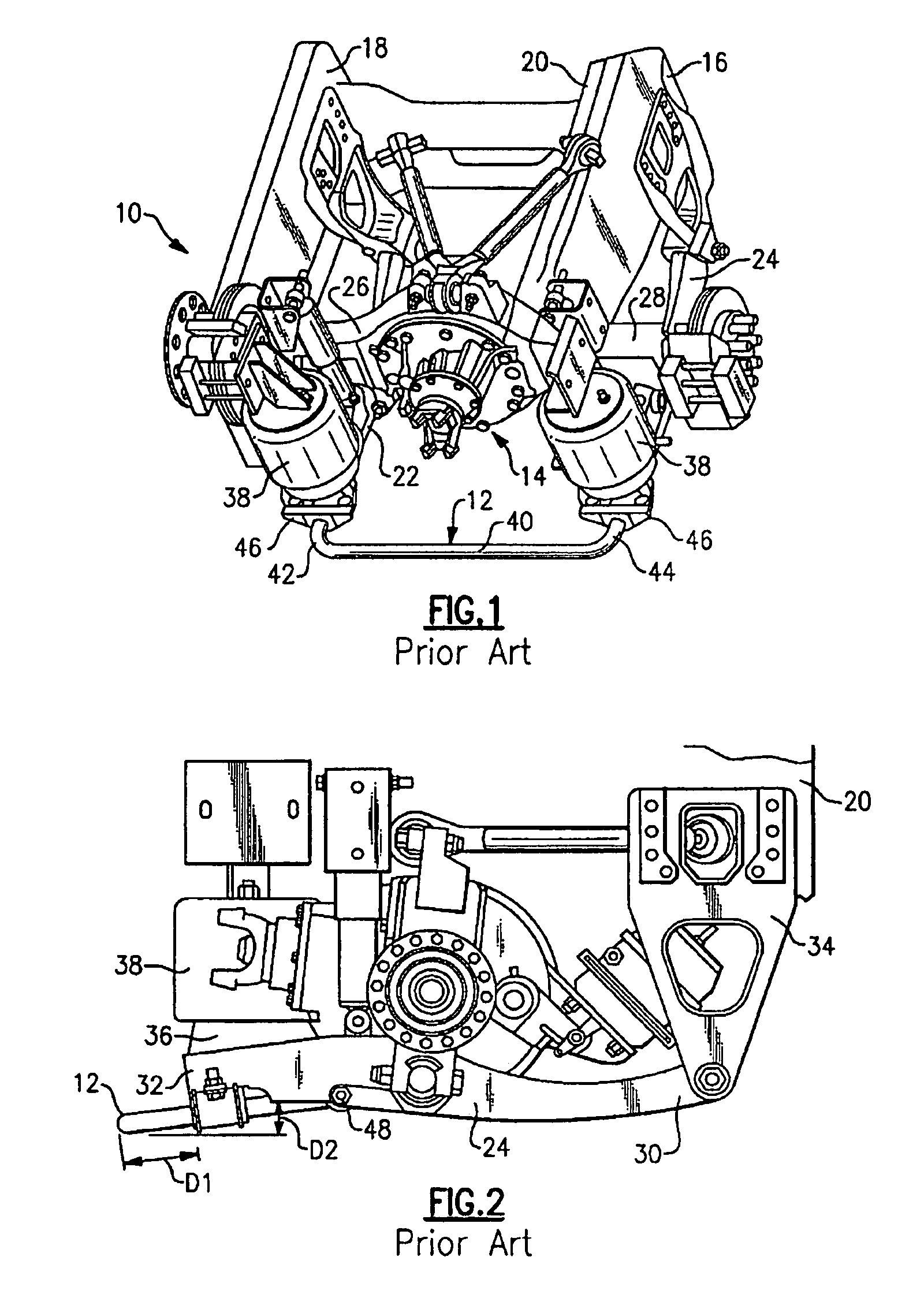
[0017]FIGS. 1 and 2 show a vehicle suspension 10 with a traditional anti-roll bar 12. The vehicle suspension 10 couples an axle 14 to a vehicle frame 16. The vehicle frame 16 includes first 18 and second 20 frame members that extend longitudinally along a length of a vehicle. The vehicle suspension 10 includes first 22 and second 24 lower control arms that extend underneath first 26 and second 28 axle housing legs, respectively.

[0018]Each of the first 22 and second 24 lower control arms includes a first end 30 and a second end 32, as shown in FIG. 2. The first end 30 is attached to a respective one of the first 18 and second 20 frame members with a bracket assembly 34. Each second end 32 includes a support plate 36 that supports a resilient member, such as an air spring 38 for example. An upper portion of each air spring 38 is attached to a respective one of the first 18 and second 20 frame members.

[0019]The anti-roll bar 12 includes a central body portion 40 and first 42 and second...


PUM


Abstract

An anti-roll bar is attached directly to first and second control arms in a vehicle suspension. The anti-roll bar includes a central body portion that extends in a lateral direction, and first and second legs that extend from the central body portion in a longitudinal direction. The first and second legs are attached to inboard surfaces of the first and second control arms. The anti-roll bar is positioned such that the central body portion does not extend outwardly beyond longitudinal ends of the first and second control arms, and does not extend vertically below lower surfaces of the first and second control arms. This configuration allows the vehicle suspension to be packaged within a smaller space, and improves ground clearance.

Description

TECHNICAL FIELD[0001]The subject invention relates to an anti-roll bar that is attached to first and second control arms such that the anti-roll bar is packaged within an envelope of space defined between the first and second control arms.BACKGROUND OF THE INVENTION[0002]Vehicle suspension systems are used to absorb road load inputs and other vibrations to provide a smooth and comfortable ride. Trailing arm or multi-link suspensions that do not have a fixed connection to an axle usually include a separate component to increase roll stiffness of the suspension to a desired level. This separate component typically comprises a stabilizer bar or anti-roll bar that provides an increased level of roll rigidity and improves steering stability.[0003]In one example, the anti-roll bar is connected to lower control arms, which are mounted to a wheel component, such as a knuckle. The anti-roll bar is generally C-shaped with first and second legs that are each attached to one control arm. Typica...

Claims


Application Information

Patent Timeline
Patent Type & Authority Patents(United States)
IPC IPC(8): B60G21/05
CPCB60G9/027B60G11/27B60G21/0551B60G2200/315B60G2202/152B60G2204/1224B60G2204/1226
Inventor REINECK, BENJAMIN R.
Owner ARVINMERITOR TECH
Why Eureka
Try Eureka