Assembly for an aircraft including a wing element and a suspension pylon

a technology of suspension pylons and aircraft, which is applied in the direction of aircraft power plants, power plant construction, power plant types, etc., can solve the problems of increasing restrictions in the space between the wing, the suspension pylons and the different attachments, and the overall dimension is extremely large, so as to achieve the effect of improving adaptability and further increasing ground clearan

Inactive Publication Date: 2010-08-05
AIRBUS OPERATIONS (SAS)
View PDF7 Cites 22 Cited by
  • Summary
  • Abstract
  • Description
  • Claims
  • Application Information

AI Technical Summary

Benefits of technology

[0014]Consequently, the assembly according to the invention enables larger dimensions of suspension pylons, so that they can be better adapted to the high forces that they are designed to resist.
[0015]Furthermore, note that this solution no longer uses conventional attachments like those described in the state of prior art, considering that in the preferable required, the entire rigid structure forming a box is located in front of the forward spar of the wing element. Fastening means for fixing the rigid structure onto the wing element can then be entirely laid out at the closing element that is normally vertical, and are no longer partially added on the upper spar of the box as was the case previously with the spigot type intermediate attachment. Thus, the presence of these fastening means does not increase the size in the vertical direction, so that the dimensions of the suspension pylon and / or the ground clearance can be further increased.

Problems solved by technology

On recent aircraft turbo-engines, the large dilution ratio required results in an extremely large overall dimension, because increasing the dilution ratio inevitably increases the engine diameter, and also more particularly increases the diameter of its fan case.
Thus, with a ground clearance that is naturally fixed so as to remain acceptable from a safety point of view, the space remaining between the wing and the turbo-engine to hold the suspension pylon and the different attachments is becoming increasingly restricted, while paradoxically the forces to be resisted are becoming increasingly high.
This development of turbo-engines has the unfortunate consequence of reducing the vertical dimensions of the suspension pylon, particularly to maintain sufficient space to put the clamping fitting of the intermediate attachment into place, for which large dimensions are necessary in order to resist the turbo-engine thrust forces, in other words forces along the longitudinal direction of the turbo-engine, and forces along the transverse direction of the turbo-engine.

Method used


Image

  • Assembly for an aircraft including a wing element and a suspension pylon
  • Assembly for an aircraft including a wing element and a suspension pylon
  • Assembly for an aircraft including a wing element and a suspension pylon

Examples


first embodiment

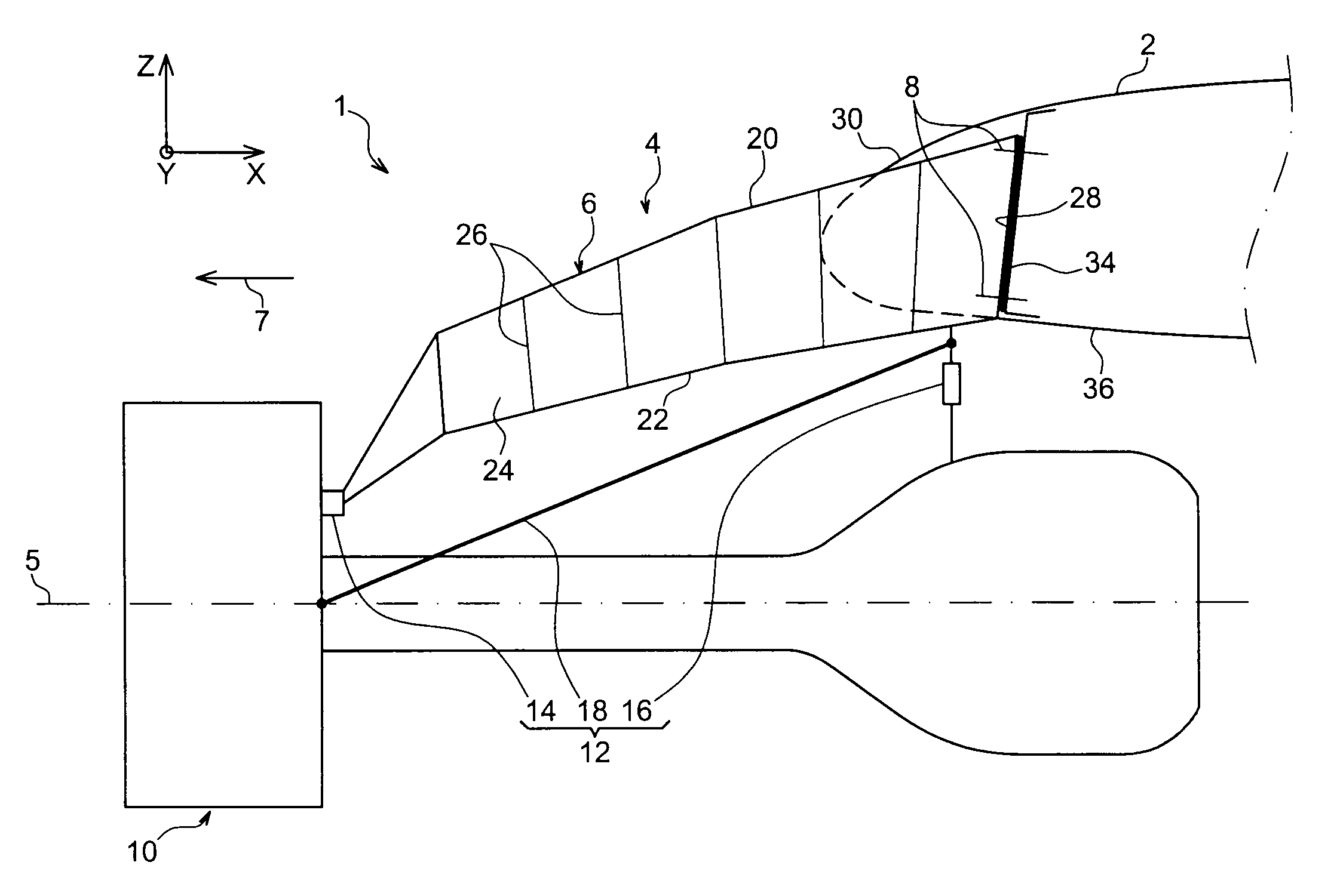
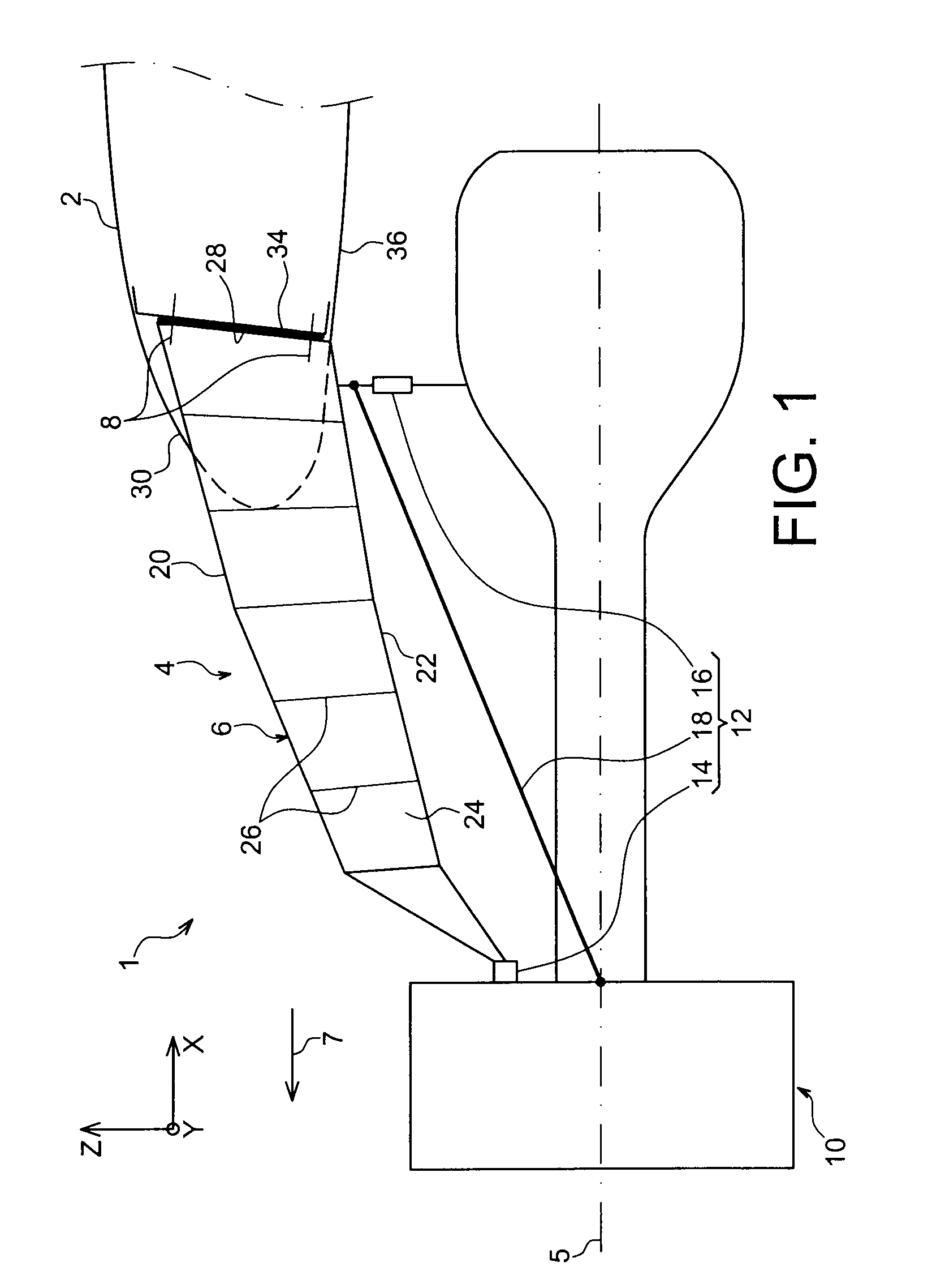
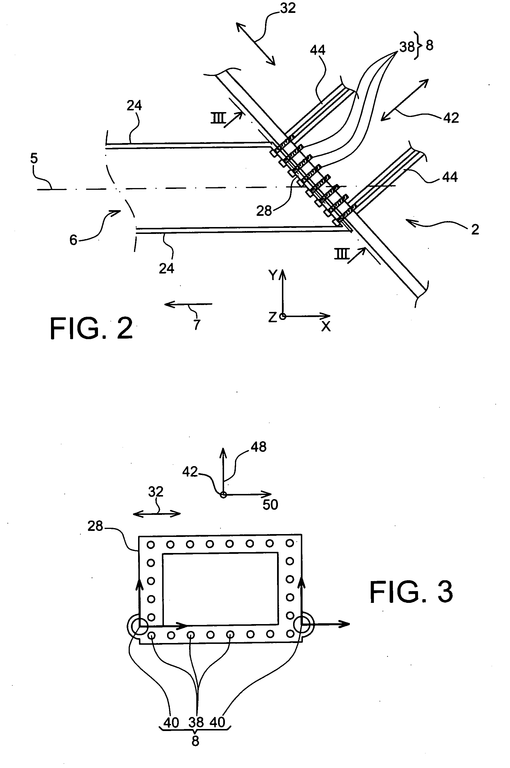
[0042]However, in the configuration shown for this first embodiment and as can be seen in FIGS. 2 and 3, the only fastening means provided between the closing element 28 and the forward spar 34 are a plurality of tension bolts 38, and two lateral shear pins 40. More precisely, these mounting means 8 preferably have a symmetry about a vertical plane parallel to a direction 42 orthogonal to the width direction 32 and therefore comprise two shear pins 40 arranged on each side of this plane (not shown), these pins 40 also being arranged along this direction 42 and therefore each of them being capable of resisting forces applied along a first and a second directions orthogonal to each other and also orthogonal to the direction 42. Note also that the above-mentioned vertical plane also preferably forms a plane of symmetry for the closing element 28.

[0043]The mounting means 8 also comprise tension bolts 38 also arranged in the direction 42 along which a plurality of force loading ribs 44 o...

second embodiment

[0047]Therefore, in this second embodiment and in the other described embodiments, the entire rigid structure 6 of the pylon 4 is preferably forwards from the forward spar 34 of the wing 2.

[0048]With reference to FIG. 5, the figure shows an assembly 1 for an aircraft according to a third preferred embodiment of this invention. In this mode, there is a support fitting 152 preferably provided with reinforcing ribs 153, and for which the lower part located outside the wing 2 is identical to or similar to the support fitting 52 described in the context of the second embodiment, and an upper part located outside the wing 2 is inserted between the forward spar 34 and the closing element 28. Thus, this final element 28 that is still bearing in contact with the spar 34 without being directly in contact with it, is consequently entirely in contact with a bearing surface 154 of the fitting 152, this surface 154 and the element 28 then being partially inside and partially outside the wing 2.

[0...


PUM


Abstract

The invention relates to an assembly for an aircraft comprising a wing element (2) and a suspension pylon (4) for an engine (10) under the wing element, the suspension pylon (4) comprising a rigid structure (6) forming a box provided with an aft closing element (28), and the wing element (2) having a forward spar (34) extending substantially parallel to a leading edge (30) of the wing element. According to the invention, the rigid structure is assembled on the wing element such that the aft closing element bears in contact with the forward spar (34).

Description

TECHNICAL DOMAIN[0001]This invention relates in general to an assembly for an aircraft comprising a wing element and an engine suspension pylon under said wing element.[0002]Such an assembly may be used for any type of aircraft, for example aircraft with turbo-engines suspended from the wing, such as turbojets or turboprops.STATE OF PRIOR ART[0003]On existing aircraft, turbo-engines are suspended below the wing by complex mounting devices, also called EMS (Engine Mounting Structure), or suspension pylon. For turbojets, the mounting devices usually used comprise a rigid box structure, in other words formed by the assembly of upper and lower spars connected to each other through a plurality of transverse ribs.[0004]In a known manner, these pylons are designed particularly to transmit static and dynamic forces generated by the turbo-engines such as the weight, thrust or the different dynamic forces, to the wing.[0005]In this respect, forces are usually transmitted between suspension py...

Claims


Application Information

Patent Timeline
Patent Type & Authority Applications(United States)
IPC IPC(8): B64D27/26
CPCB64D27/18B64D2027/264B64D27/26
Inventor LAFONT, LAURENT
Owner AIRBUS OPERATIONS (SAS)
Why Eureka
Try Eureka