Mounting System for an Internal Bicycle Transmission

a technology for bicycle transmissions and mounting systems, applied in mechanical devices, transportation and packaging, gearing, etc., can solve the problems of increased likelihood of chain derailment, increased resistance to shock, and reduced resistance, so as to improve packaging and ground clearance

Inactive Publication Date: 2008-10-16
SRAM CORPORATION
View PDF8 Cites 22 Cited by
  • Summary
  • Abstract
  • Description
  • Claims
  • Application Information

AI Technical Summary

Benefits of technology

[0005]A bicycle transmission is provided that is mountable to a bottom bracket shell of a bicycle frame for improved packaging and ground clearance. The bicycle transmission generally includes an input crank assembly, an output chainring for engaging a bicycle drive chain, a planetary gear mechanism, a control system and a mounting system. The planetary gear mechanism includes a ring gear and is mounted coaxially about an axis of the bottom bracket shell. The planetary gear mechanism provides a plurality of transmission paths. The control system is operatively connected to the planetary gear mechanism for selecting one of the transmission paths. The mounting system mounts the planetary gear mechanism and the control system to the bottom bracket shell. The bicycle drive chain includes a plurality of chain links. In one embodiment of the present invention, at least one of the chain links overlaps the ring gear as viewed along the shell axis. The at least one chain link engages the output chainring.

Problems solved by technology

This reactive torque may be substantial.
However, a disadvantage of a smaller chainring is the increased likelihood of chain derailment because there are fewer teeth engaging the chain.
One disadvantage of these configurations is that additional elements are mounted to the bottom bracket shell, requiring a redesign of the bottom bracket.
Another disadvantage of the configuration that uses of the face of the bottom bracket for axially pinching the ground plate, is that it takes up extra space axially, resulting in a longer axle and a wider stance between pedals.

Method used


Image

  • Mounting System for an Internal Bicycle Transmission
  • Mounting System for an Internal Bicycle Transmission
  • Mounting System for an Internal Bicycle Transmission

Examples


Embodiment Construction

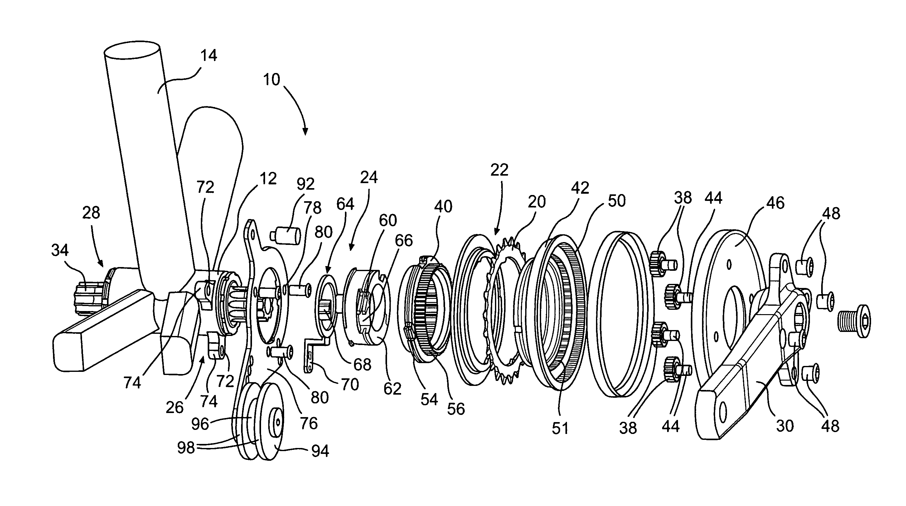
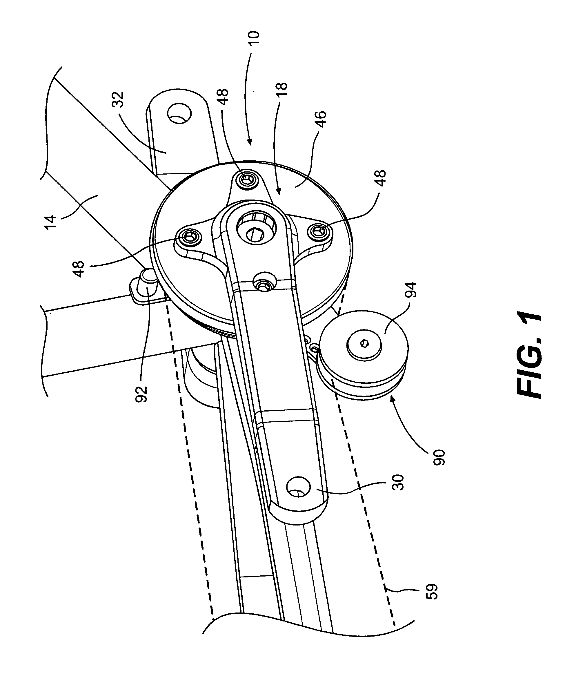
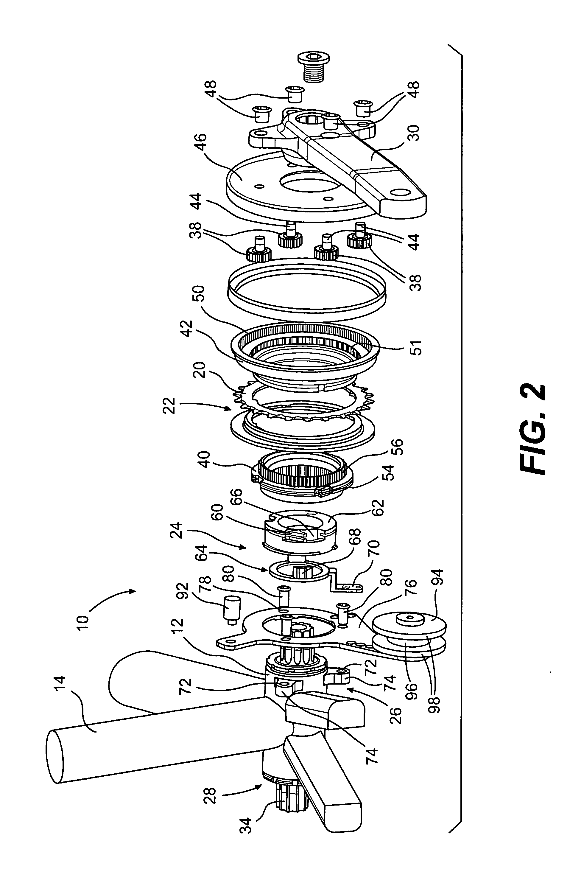
[0019]FIGS. 1-11 illustrate a bicycle transmission assembly 10 according to one embodiment of the present invention. Looking to FIGS. 1-4, the bicycle transmission assembly 10 is externally mounted to a bottom bracket shell 12 of a bicycle frame 14. The bottom bracket shell 12 has an axis 16 and connects various tubes of the bicycle frame 14. The bicycle transmission assembly 10 generally includes an input crank assembly 18, an output chainring 20, a planetary gear mechanism 22, a control system 24 and a mounting system 26. The crank assembly 18 is rotatably mounted to the bottom bracket shell 12. The crank assembly 18 includes a bottom bracket 28 that extends through the bottom bracket shell 12, with first and second crank arms 30, 32 rotatably connected to a crank axle 34. The bottom bracket 28 includes the crank axle 34 and bearings 36.

[0020]The planetary gear mechanism 22 is mounted coaxially about the shell axis 16 and disposed inboard of the first crank arm 30. The planetary g...


PUM


Abstract

A bicycle transmission assembly that is mountable to a bottom bracket shell of a bicycle frame. The bicycle transmission generally includes an input crank assembly, an output chainring, a planetary gear mechanism, a control system and a mounting system. The output chainring engages a bicycle drive chain that includes a plurality of chain links. The planetary gear mechanism includes a ring gear and provides a plurality of transmission paths. The planetary gear mechanism is mounted coaxially about the shell axis. The control system is operatively connected to the planetary gear mechanism for selecting one of the plurality of transmission paths. The mounting system mounts the planetary gear mechanism and the control system to the bottom bracket shell. At least one chain link overlaps the ring gear as viewed along the shell axis. The at least one chain link engages the output chainring.

Description

RELATED APPLICATION DATA[0001]This application is a continuation-in-part of U.S. application Ser. No. 11 / 734,236 filed on Apr. 11, 2007, entitled “Mounting System for an Internal Bicycle Transmission.”BACKGROUND OF THE INVENTION[0002]The present invention relates to internal bicycle transmissions and more particularly to a mounting system for mounting an internal bicycle transmission to a bottom bracket shell.[0003]Internal bicycle transmissions may be located at the rear wheel hub and / or at the front crank assembly. Internal bicycle transmissions provide multiple transmission paths corresponding to multiple bicycle gear ratios. Typically, an internal bicycle transmission includes a planetary gear mechanism with a sun gear, a ring gear, a plurality of planet gears meshing with the ring gear, and sun gear and a carrier for supporting the planet gears. To shift between the multiple transmission paths, select elements of the planetary gear mechanism may be locked or unlocked. For examp...

Claims


Application Information

Patent Timeline
Patent Type & Authority Applications(United States)
IPC IPC(8): F16H9/26
CPCB62M9/16B62M11/145
Inventor WESLING, KEVINSHIPMAN, CHRISTOPHERJORDAN, BRIAN
Owner SRAM CORPORATION
Why Eureka
Try Eureka