Refresh controller and address remapping circuit and method for dual mode full/reduced density DRAMs

a controller and address remapping technology, applied in the field of dynamic random access memories, can solve the problems of excessive power consumption, and achieve the effect of reducing density mode and excessive power consumption

Inactive Publication Date: 2002-09-12
ROUND ROCK RES LLC
View PDF2 Cites 12 Cited by
  • Summary
  • Abstract
  • Description
  • Claims
  • Application Information

AI Technical Summary

Benefits of technology

0009] A refresh controller is used in a synchronous dynamic random access memory having a full density mode and a reduced density mode. The refresh controller refreshes the SDRAM at a first rate when the SDRAM is operating in the full density mode and at a second rate that is slower than the first rate when the SDRAM is operating in the reduced density mode. The refresh controller functions in this manner in both an auto-refresh mode, in which external refresh command are applied to the SDRAM, and in a self-refresh mode, in which periodic refresh commands are internally generated. For operation in the self-refresh mode, the refresh controller preferably includes an oscillator generating a first periodic clock signal, which is applied to a frequency division circuit to generate a second periodic clock signal having a frequency that is less than the frequency of the first periodic signal. A first selector circuit is preferably used to apply the first periodic clock signal to an output terminal in the full density mode and to apply the second periodic clock signal to the output terminal in the reduced density mode. A counter may be coupled to the output terminal of the first selector circuit. A second selector circuit preferably couples a first stage of the counter to an output terminal in the full density mode and a different stage of the counter to the output terminal in the reduced density mode. The output of the second selector circuit is then used to trigger a refresh of the SDRAM. For operation in the auto-refresh and self-refresh modes, the refresh controller preferably includes an auto-refresh circuit that ignores a predetermined percentage of the externally applied auto-refresh commands and processes the remaining auto-refresh commands. Conventional memory controllers (not shown) must apply a specific number of auto-refresh commands to an SDRAM device to refresh every row in the memory device. The specific number of auto-refresh commands that must be applied is a function of the capacity of the memory device. In the half density mode, only half as many auto-refresh commands are required to refresh every row in the memory device because two rows are refreshed for every auto-refresh command. However, if a half-density SDRAM is used in a system in place of a full-density SDRAM, the memory controller or other device will continue to apply the number of auto-refresh commands that the full-density SDRAM requires. As a result, each row in the half-density SDRAM will be refreshed far more frequently than is required, thereby excessively consuming power.

Problems solved by technology

As a result, each row in the half-density SDRAM will be refreshed far more frequently than is required, thereby excessively consuming power.

Method used


Image

  • Refresh controller and address remapping circuit and method for dual mode full/reduced density DRAMs
  • Refresh controller and address remapping circuit and method for dual mode full/reduced density DRAMs
  • Refresh controller and address remapping circuit and method for dual mode full/reduced density DRAMs

Examples


Embodiment Construction

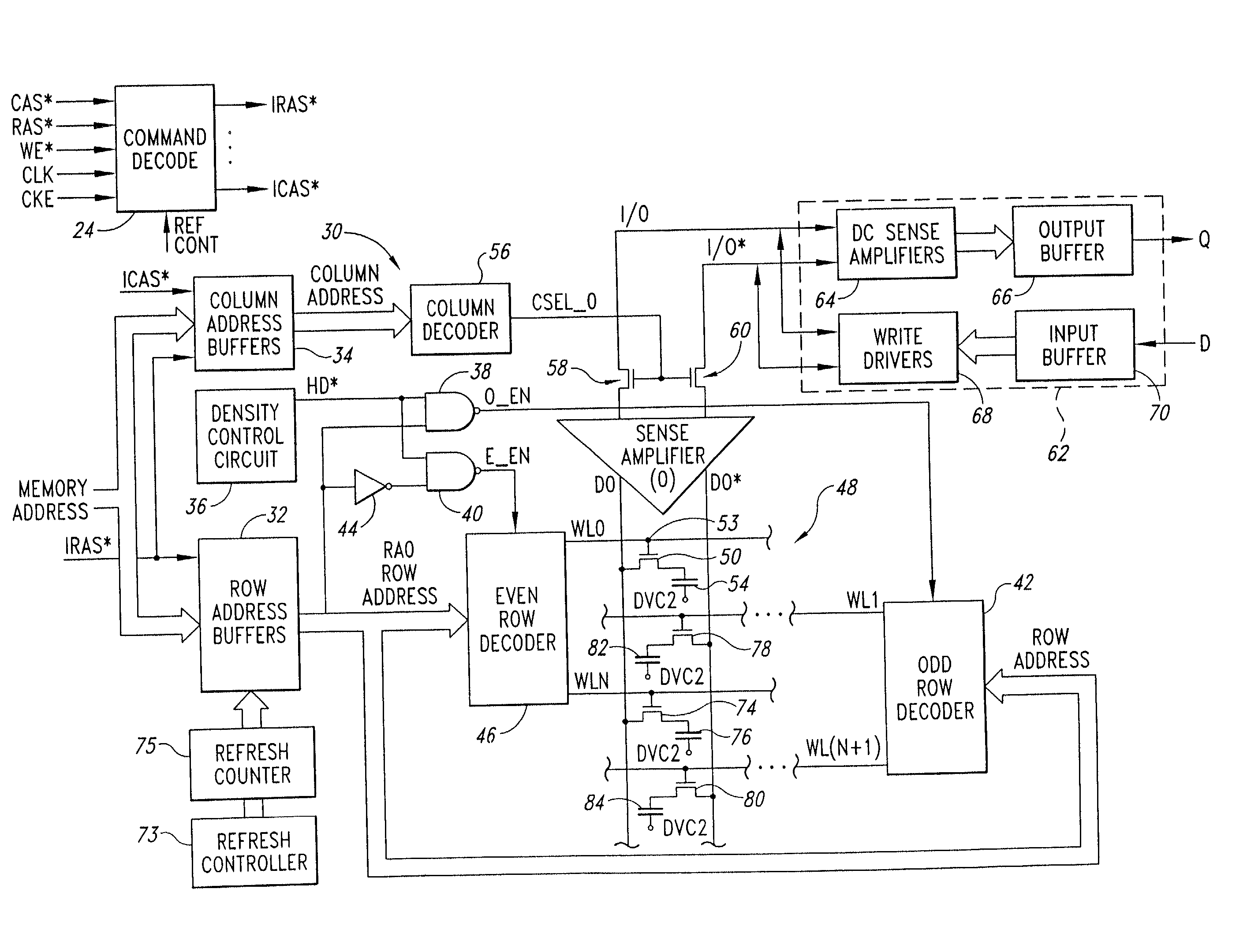
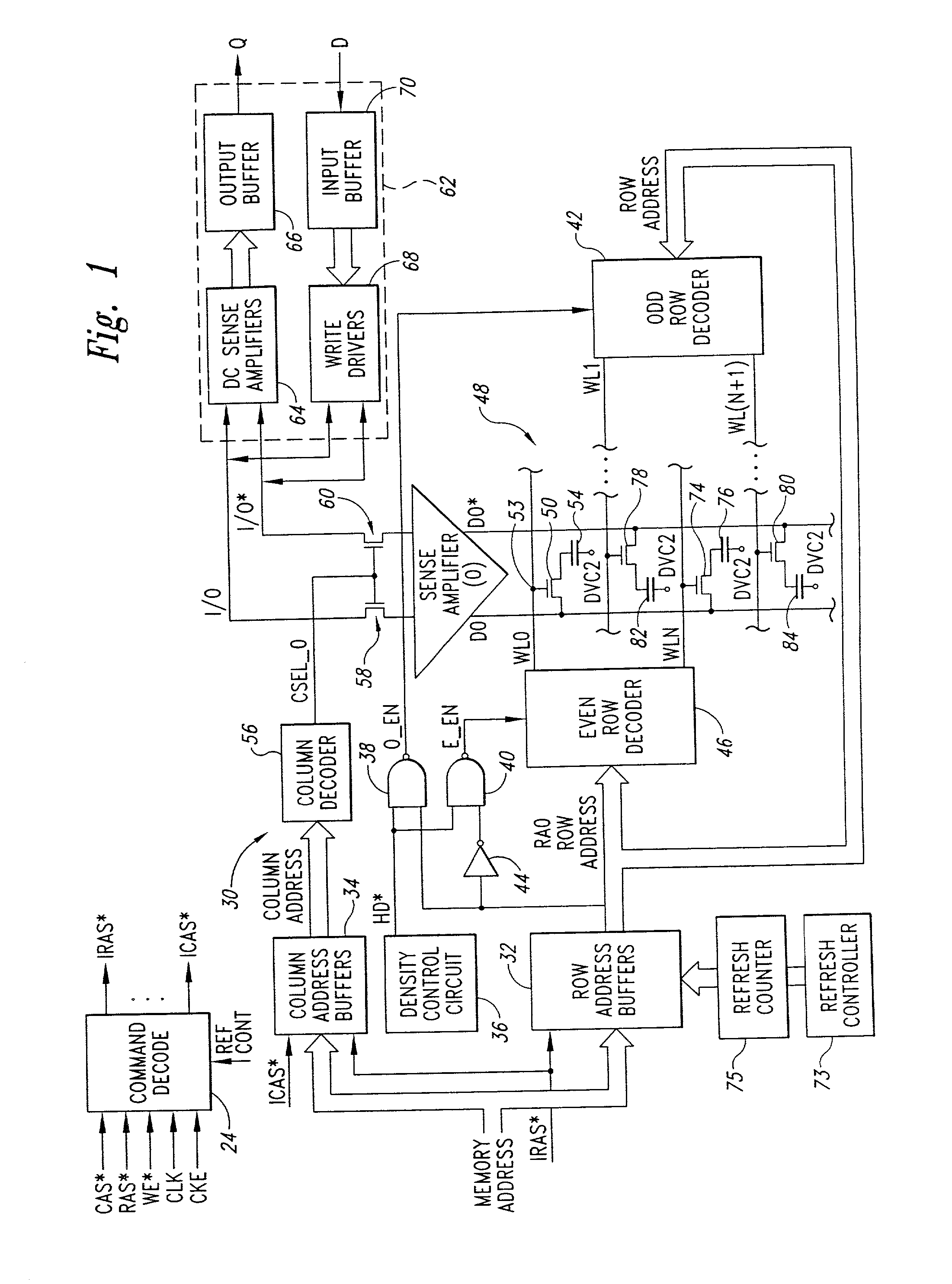
[0016] FIG. 1 is a block diagram of a synchronous dynamic random access memory ("SDRAM") 20 according to one embodiment of the invention. The SDRAM 20 includes row and column address buffers 32 and 34 receiving a time-multiplexed row and column addresses, respectively. The SDRAM 20 also includes a command decoder 24 receiving several command signals, including a row address strobe signal RAS*, a column address strobe signal CAS*, a write enable signal WE*, a clock signal CLK, and a clock enable signal CKE. As is well known in the art, various combinations of these command signals correspond to respective memory commands, such as activate, read, write, precharge, etc. The command decoder 24 then generates control signals corresponding to the memory commands, including a read command and a write command. Two of the control signals generated by the command decoder 24 are an internal row address strobe signal IRAS and an internal column address strobe signal ICAS*. It will be understood...


PUM


Abstract

A dual mode, full density/half density SDRAM includes a refresh controller specifically adapted to refresh memory cells of the SDRAM in the half density mode at a rate that is significantly slower than the rate at which the memory cells are refreshed in the full density mode. In the full density mode, the refresh controller increments a counter at a rate that is half the rate the counter is incremented in the full density mode. A refresh trigger pulse, which initiates the refresh of the memory cells, is generated when the counter has incremented to one of a first counter stage in the full density mode and a counter stage two stages beyond the first counter stage in the half density mode. Circuitry is also provided for ignoring some auto-refresh commands applied to the SDRAM in the half density mode so that the memory cells are also refreshed less frequently in the auto-refresh mode. The SDRAM also includes circuitry for remapping one of the row address bits for use as a column address bit in the half density mode so that the SDRAM can interface with system adapted for conventional dual mode SDRAMs.

Description

TECHNICAL FIELD[0001] The invention relates to dynamic random access memories ("DRAMs") and, more particularly, to a system and method for optimally controlling the refresh and addressing of DRAMs operating in either a full density mode or a reduced density mode, such as a half density mode.BACKGROUND OF THE INVENTION[0002] DRAMs use one or more arrays of memory cells arranged in rows and columns. Each of the rows of memory cells is activated by a corresponding row line, which is selected from a row address. A pair of complementary digit lines are provided for each column of the array, and a sense amplifier coupled to the digit lines for each column is enabled responsive to a respective column address. The sense amplifier senses a small voltage differential between the digit lines and amplifies such voltage differential. In a "folded digit line" memory architecture, the complementary digit lines extend through the same array. In the typical folded digit line architecture, the memory...

Claims


Application Information

Patent Timeline
Patent Type & Authority Applications(United States)
IPC IPC(8): G11C7/10G11C11/406
CPCG11C7/1045G11C7/1072G11C11/406
Inventor COWLES, TIMOTHY B.SHORE, MICHAEL A.MULLARKEY, PATRICK J.
Owner ROUND ROCK RES LLC
Why Eureka
Try Eureka