

Automated system and method for withdrawing compounds from blood
- Summary
- Abstract
- Description
- Claims
- Application Information
AI Technical Summary
Benefits of technology
Problems solved by technology
Method used
Image

Examples
Embodiment Construction
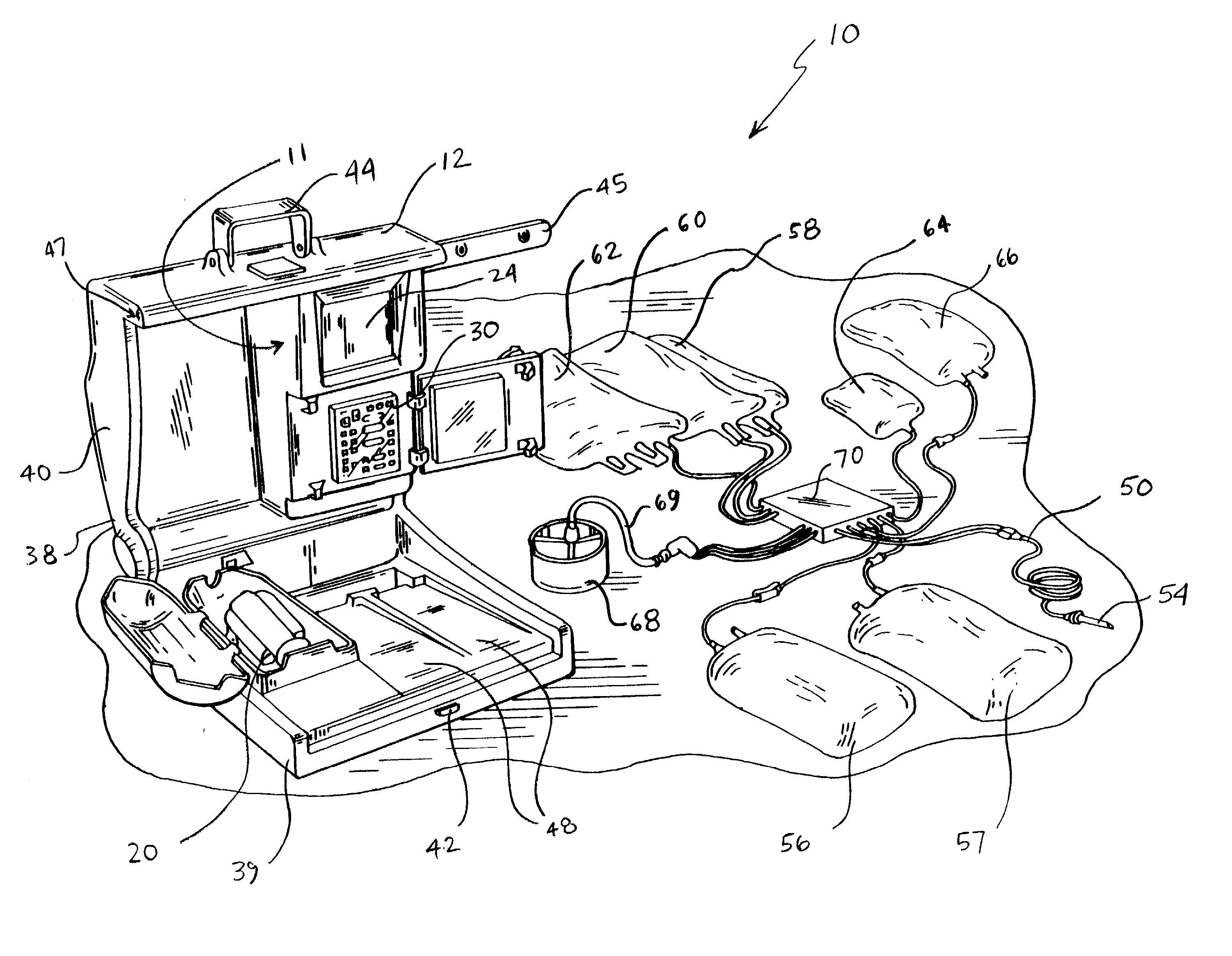
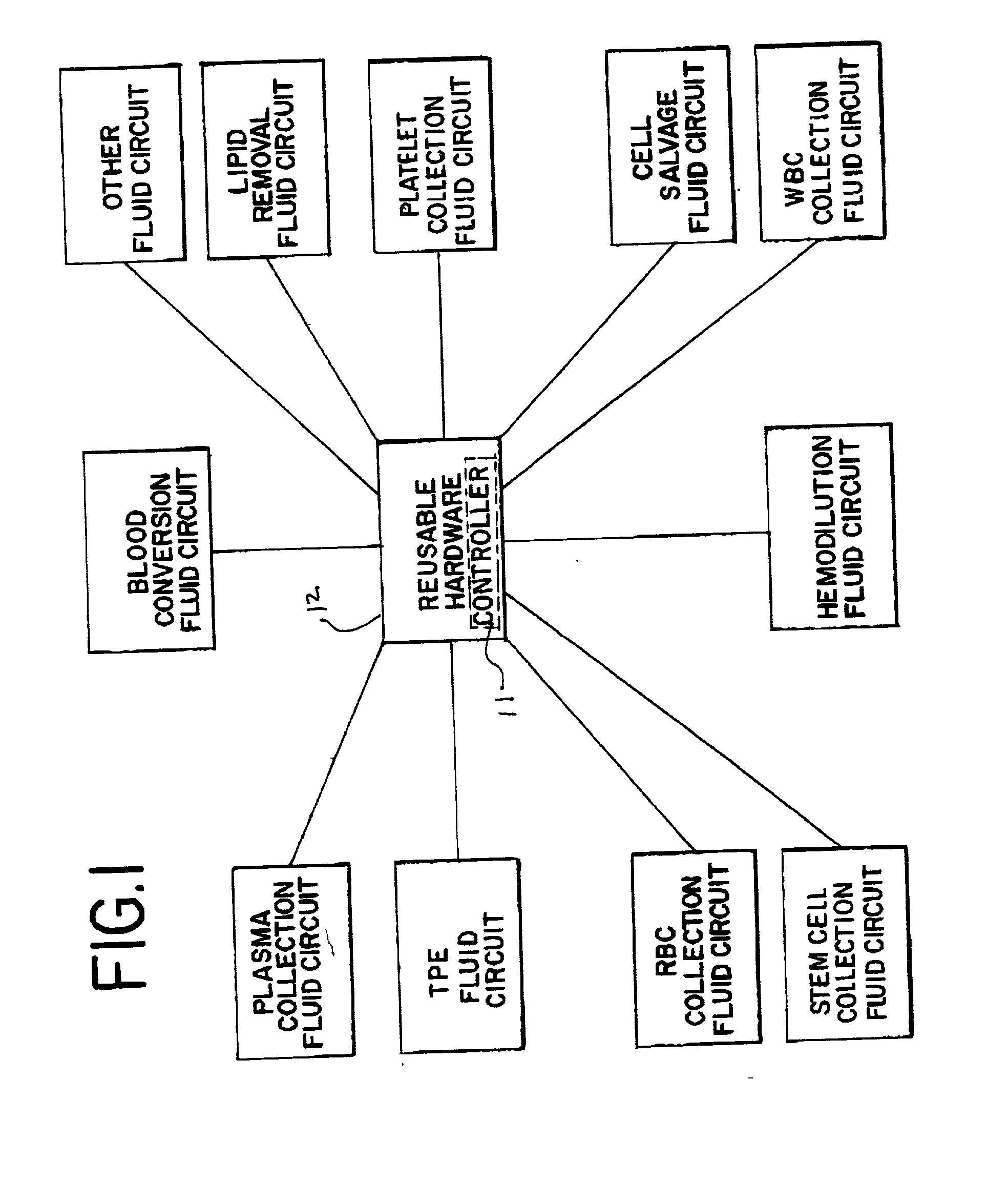
[0041] Turning now to the drawings, FIG. 1 diagrammatically shows a multi-purpose blood and fluid processing system 10 embodying the present invention.
[0042] As generally shown in FIG. 1, automated system 10 includes a re-usable hardware component or module 12. The re-usable hardware component 12 is particularly versatile and may be used with a variety of disposable fluid circuits. Thus, for example, hardware component 12 can be used with fluid circuits for red blood cell collection, plasma collection, platelet collection, white blood cell (leukocyte) collection, stem cell collection, hemodilution, cell salvage, lipid removal from plasma, conversion of red blood cells, cell washing, red blood cell exchange, leukoreduction, other therapeutic plasma treatments and, as will be seen, combinations of such procedures.
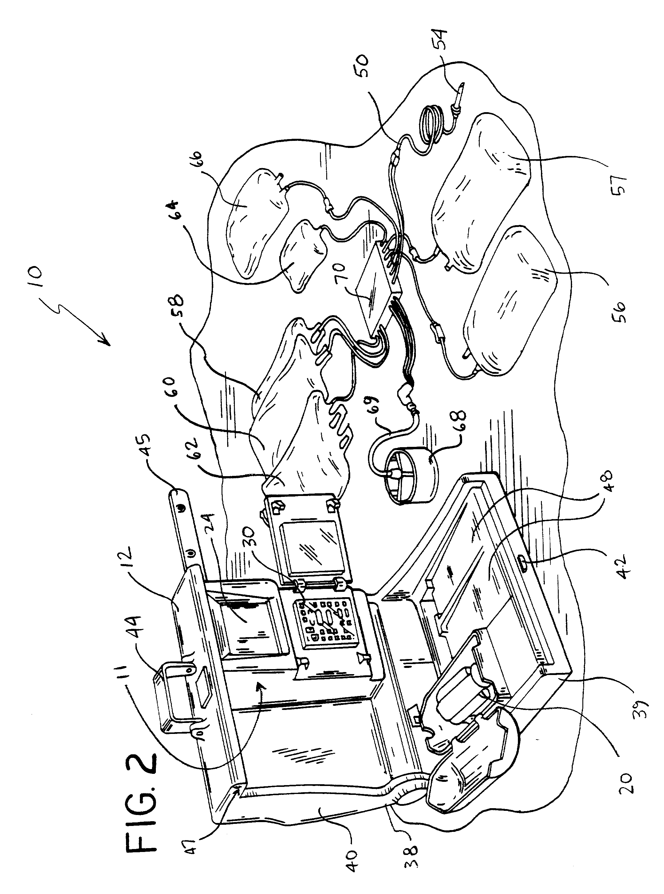
[0043] One embodiment of the automated, multi-purpose blood and fluid processing system that may incorporate the present invention is shown in FIG. 2. As shown in FIG. 2, aut...
PUM
 Abstract
Description
Claims
Application Information