Stem cell collecting device

A collection device and stem cell technology, applied in the field of stem cell collection, can solve problems such as general cleaning effect, pollution, and difficulty in cleaning

Active Publication Date: 2020-10-27
湖北明德健康科技有限公司
View PDF9 Cites 3 Cited by
  • Summary
  • Abstract
  • Description
  • Claims
  • Application Information

AI Technical Summary

Problems solved by technology

[0004] In the prior art, in the patent with the publication number CN208532796U, the cleaning nozzle can be installed to clean the remaining blood stains in the used blood storage chamber and stem cell separator, so as to avoid the residual blood stains from polluting the

Method used


Image

  • Stem cell collecting device
  • Stem cell collecting device
  • Stem cell collecting device

Examples


Embodiment 1

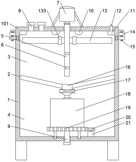
[0029] see Figure 1-3, the present invention provides a technical solution: a stem cell collection device, comprising a box 1, the bottom of the box 1 is symmetrically fixed with supporting legs, and the bottom of the supporting legs is fixed to a plane. The inner wall of the box body 1 is divided into a blood storage chamber 3 and a separation chamber 4 through the partition plate 2, and the top of the box body 1 is provided with a cover 101, the top of the box body 1 is provided with a guide groove, and the bottom end of the cover body 101 is fixed with a guide rod to guide The rods are correspondingly plugged into the guide grooves. Multiple sets of fastening components are arranged between the box body 1 and the cover body 101, and each set of fastening components includes two connecting blocks 14, one of which is fixed to the cover body 101, and the other connecting block 14 is fixed to the box body 1 , the two connecting blocks 14 are correspondingly fastened through t...

Embodiment 2

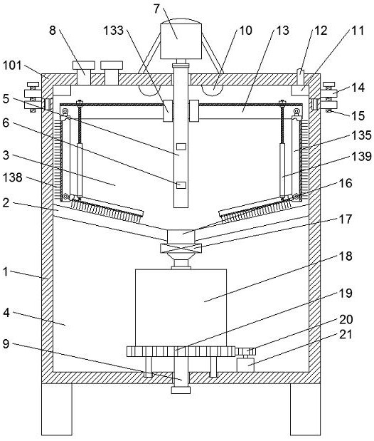
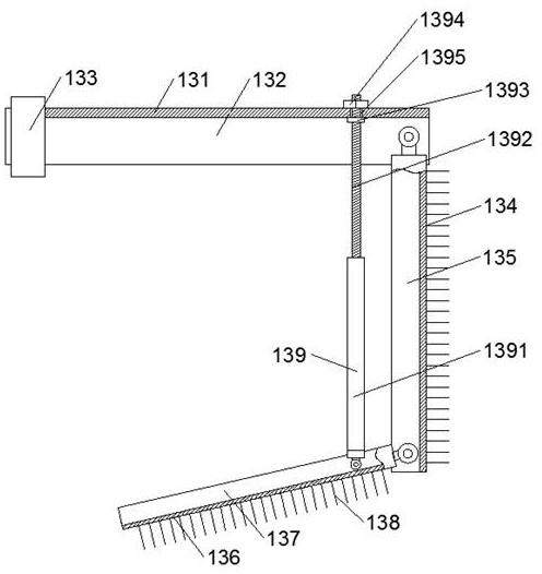
[0033] On the basis of embodiment one, refer to Figure 4-6 , each group of stirring rods 6 includes two adjacent stirring rods 6 up and down. The inner ends of each group of stirring rods 6 are rotatably connected to the rotating shaft 5 ; and the outer ends of each group of stirring rods 6 are fixed with the same moving rod 22 . An iron block 23 is fixed on the top of the moving rod 22, a magnetic block 24 is fixed on the inner wall of the blood storage chamber 3 corresponding to the position above the iron block 23, a supporting block 25 is fixed on the rotating shaft 5 corresponding to the upper position of the stirring rod 6, and the supporting block 25 and the stirring rod A plurality of springs 26 are fixed between the 6.

[0034] The rotation of the rotating shaft 5 drives the stirring rod 6 and the moving rod 22 to rotate. When the iron block 23 fixed on the top of the moving rod 22 is close to the magnetic block 24, the iron block 23 moves up, which drives the movin...


PUM


Abstract

The invention discloses a stem cell collecting device in the field of stem cell collection. The device comprises a box body, wherein the inner wall of the box body is divided into a blood storage chamber and a separation chamber through a partition plate, a rotating shaft is rotationally connected to the center of the top wall of a cover body, a cleaning assembly is arranged above the rotating shaft, the bottom end of the partition plate communicates with a liquid discharging pipe with an electromagnetic valve, and the bottom end of the liquid discharging pipe is rotationally connected and communicates with a stem cell separator. By additionally arranging the cleaning assembly, when the blood storage chamber needs to be cleaned, a rotating ring is rotated to move towards the inner side, avertical rod and an inclined rod are separated from the first cavity and the second cavity correspondingly, a limiting assembly is rotated, and then a sleeve is rotated, so that a first screw penetrates through a through hole and is locked through a nut, clear water is sprayed out of an annular spraying pipe; a first motor drives the cleaning assembly to rotate to clean the inner wall of the bloodstorage chamber, residual blood stains can be fully cleaned under the combined action of the clear water and a cleaning brush, and the cleaning effect is good; the cleaning assembly is not in contactwith blood, and the cleaning brush is prevented from polluting blood.

Description

technical field [0001] The invention relates to the technical field of stem cell collection, in particular to a stem cell collection device. Background technique [0002] Stem cells are cells with proliferation and differentiation potential, have the ability of self-renewal and replication, and can produce highly differentiated functional cells. Simply put, it is a type of primitive undifferentiated cell with multi-directional differentiation potential and self-replication ability, and is the original cell that forms various tissues and organs of mammals. Stem cells are common in shape, usually round or oval, small in size, relatively large in nucleus, mostly euchromatin in nucleus, and have high telomerase activity. Stem cells can be divided into embryonic stem cells and adult stem cells. Whether stem cells are self-replicating or differentiated functional cells is mainly determined by the state of the cells themselves and microenvironmental factors. Includes various cyc...

Claims


Application Information

Patent Timeline
IPC IPC(8): C12M1/12C12M1/02C12M1/00B08B9/087B08B9/093
CPCB08B9/087B08B9/093C12M23/34C12M23/38C12M23/46C12M27/02C12M37/00C12M39/00C12M47/04
Inventor 陈飞杨方园
Owner 湖北明德健康科技有限公司
Why Eureka
Try Eureka