Drug solution infusion catheter

a technology of infusion catheter and drug solution, which is applied in the direction of catheters, suction devices, other medical devices, etc., can solve the problems of blood clot formation, the catheter cannot be inserted along the guide wire, and the distal end of the catheter cannot be inserted, so as to prevent blood clot formation

Active Publication Date: 2012-02-14
PIOLAX MEDICAL DEVICES
View PDF15 Cites 1 Cited by
  • Summary
  • Abstract
  • Description
  • Claims
  • Application Information

AI Technical Summary

Benefits of technology

[0012]Accordingly, the invention provides a drug solution infusion catheter in which backflow of blood into the catheter is prevented, drug solution can be infused to an intended position, blood clot due to retention of blood is prevented, and the guide wire can be inserted smoothly either from the distal end side or the base end side, whereby workability and safety during indwelling operation and operation for correcting the indwelled position of the catheter is improved.
[0014]According to this structure, when the drug solution is infused into the catheter, the hole or the incision defined in the distal end wall of the catheter is resiliently opened by the pressure of the drug solution along the direction of infusion of the drug solution, so that the drug solution is infused into an intended site. When the infusion of the drug solution is terminated, the distal end wall is resiliently restored and closed. Hence, backflow of blood into the catheter is prevented, and blood clot due to invasion of blood into the catheter during indwelling of the catheter is also prevented.
[0017]When an operator desires to correct the indwelled position of the guide wire after having inserted the catheter, the correction can be achieved in the following manner. The guide wire is inserted from the rear end side of the catheter, the guide wire is caused to be projected from the distal end portion of the catheter, the distal end thereof is moved to the intended site, and the catheter is inserted along the guide wire. Therefore, workability of the catheter indwelling operation is improved, a burden of the patient is alleviated, and the operation of a medical profession is facilitated.
[0019]According to this structure, since the center portion of the distal end wall is recessed in a taper shape or a spherical shape, the guide wire is guided to the center portion of the distal end wall by pressing the guide wire from either inside or outside of the distal end wall of the catheter, whereby the hole or the incision defined in the center portion of the distal end wall opens to allow the guide wire to be inserted therethrough easily. Even when blood is flowed in the spherical shape recess on the distal end wall of the catheter, blood is flowed out without staying there for a long time. Hence, formation of blood clot or the like can be prevented.
[0020]According to the drug infusion catheter according to the invention, since the guide wire can be inserted from either of distal end side or rear end side of the catheter, the catheter can be inserted along the guide wire, which has been inserted in the blood vessel in advance. Also, when it is desired to correct the position of the distal end portion of the catheter, the position can be corrected by inserting the guide wire from the rear end side of the catheter. Since there is no recess, which may cause retention of blood at the distal end portion of the catheter, blood clot can be prevented.

Problems solved by technology

Since the catheter disclosed in JP-A-Sho.61-187872 is provided with the duckbill one-way valve at the distal end thereof, it is possible to insert the guide wire from the base end side of the catheter, but it is difficult to insert the guide wire from the distal end side of the catheter.
Therefore, the above-described catheter cannot be inserted along the guide wire.
Consequently, the retained blood is coagulated and may result in blood clot.
However, since the catheter of JP-U-Hei.4-27946 has the check valve being recessed into a U-shape, it is difficult to insert the guide wire from the base end side of the catheter even through it is easy to insert the guide wire from the distal end of the catheter.
Hence, there arises a problem in workability in the case of correcting the indwelled position of the catheter.

Method used


Image

  • Drug solution infusion catheter
  • Drug solution infusion catheter
  • Drug solution infusion catheter

Examples


Embodiment Construction

[0030]Referring now to FIGS. 1 to 9, a drug solution infusion catheter according to an embodiment of the invention will be described.

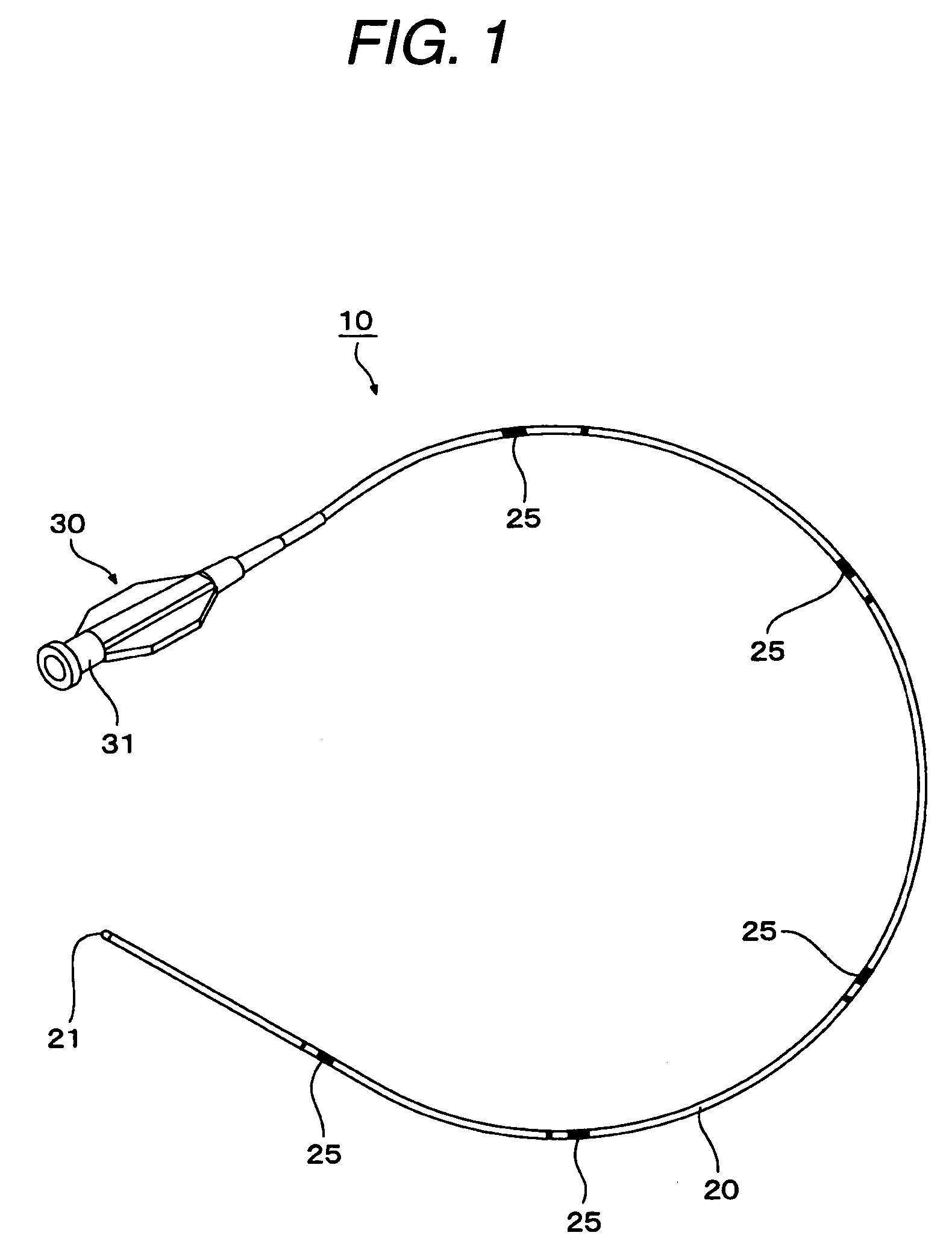
[0031]As shown in FIG. 1, a drug solution infusion catheter 10 (hereinafter, referred to simply as catheter 10) includes a catheter main body 20 of a tubular shape, which is made of synthetic resin such as polyurethane, polyamide, polyethylene, polypropylene, silicone, polyvinyl chloride, polyvinyl alcohol, polyvinyl acetate, polystyrene, polyester, polybutadiene; a derivative thereof; a copolymer thereof; a natural high polymer compound such as natural rubber, or a mixture thereof. The catheter main body 20 includes a hub 30 connected to the base end thereof. The hub 30 has a flat shape so as to be easy to grip by hand, and includes an induction pipe 31, which communicates with the catheter main body 20. A guide wire 60 described later is inserted through the induction pipe 31 of the hub 30.

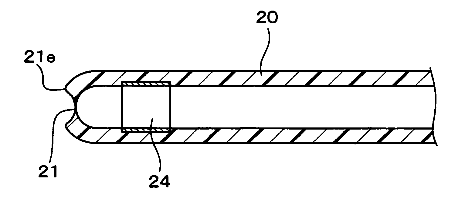
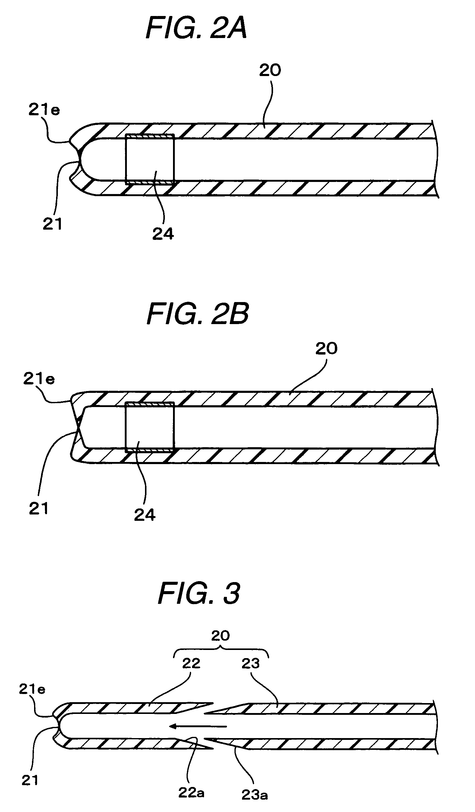
[0032]The catheter main body 20 is closed at the distal end ...


PUM


Abstract

A drug solution infusion catheter includes a distal end wall made of an elastic material. The distal end wall closes a distal end surface of the catheter. A center portion of the distal end wall is thinner than a peripheral edge portion of the distal end wall. The center portion of the distal end wall defines a hole or an incision. The hole or the incision closes normally. When a guide wire is pressed against the hole or the incision from an inner side of the catheter or an outer side of the catheter, the hole or the incision elastically opens to allow the guide wire to pass therethrough. An outside of the peripheral edge portion of the distal end wall makes up the distal end surface of the catheter.

Description

BACKGROUND OF THE INVENTION[0001]1. Field of the Invention[0002]The invention relates to a drug solution infusion catheter, which is indwelled continuously or temporarily in a blood vessel such as an artery or a vein, for infusing drug solution such as anticancer drug.[0003]2. Description of the Related Art[0004]Recent years, when administering drug solution such as anticancer drug into a body, infusion of drug solution into a cancer-ridden internal organ is now being performed by inserting a catheter into a blood vessel percutaneously and placing a distal end of the catheter at an entrance of an artery, which continue to the internal organ in question, instead of using an injection syringe or drip infusion.[0005]The catheter is inserted into the blood vessel by a well-known Seldinger technique. In other words, normally, an introduction needle formed of metal is inserted into the blood vessel percutaneously, and then a guide wire is inserted into the blood vessel through the introdu...

Claims


Application Information

Patent Timeline
Patent Type & Authority Patents(United States)
IPC IPC(8): A61M37/00A61M25/00A61M25/01A61M39/00
CPCA61M25/0068A61M25/0074A61M25/0075A61M25/0108
Inventor SAKAI, SHINICHI
Owner PIOLAX MEDICAL DEVICES
Why Eureka
Try Eureka