
Firearm bore sight system

a sight system and bore technology, applied in the field of bore sighting for firearms, can solve the problems of jarring the firearm, inconvenient operation, and inability to meet the requirements of the above-mentioned process,

Inactive Publication Date: 2002-09-19
HUNT'S
View PDF0 Cites 43 Cited by
  • Summary
  • Abstract
  • Description
  • Claims
  • Application Information

AI Technical Summary

Problems solved by technology

While this process is typically satisfactory for the shooter, a considerable amount of time and a degree of expense are involved.
The above "sighting in" process may not be available in certain situations.
For example, a hunter may jar the firearm and upset the previous sight adjustments.
The hunter may be in a situation where the typical process for "sighting in" the weapon is not possible or advisable.
This is especially true in situations where the discharge of the firearm could have a negative effect on hunting situations.
Further, access to a proper target range is not always easily available.
However, the mounting of a laser in the muzzle end of a firearm does not necessarily lead to an accurate representation of the path a bullet will travel to a selected spot on a target.
A very slight misalignment of the laser beam from this point will result in huge magnification of the error at even relatively short distances.
This patent, while describing a substantial improvement over prior forms of optical bore sighting devices, included accuracy problems.
The lens for the laser was provided separately from the laser module and could be subject to misalignment.
A misadjustment of the set screws or even a temperature change or jolt could affect the mounting arrangement and cause misalignment of the laser beam, thereby negatively affecting the sighting performance of the device.
A difficulty stemming from use of an adjustable bore sight of the type inserted within the firing chamber of a firearm, is that the beam generated by the optics must not impinge on the sidewalls of the firearm bore.
If this happens, the beam becomes diffused and will not produce an accurate indication of the bore axis.
Further, it is very difficult to withdraw the sighting unit and make adjustments that are meaningful.
The typical casing is substantially cylindrical and can be rotated, either intentionally or unintentionally and this factor seriously affects any potential adjustments that might be made.
However, the adjustment screws allow for tampering and a slight misalignment of the device could lead to an attempt by the owner or operator to readjust the unit, thereby seriously misaligning the device and frustrating the intent to provide an accurate sighting device.

Method used


Image

  • Firearm bore sight system
  • Firearm bore sight system
  • Firearm bore sight system

Examples


Embodiment Construction

[0020] This disclosure of the invention is submitted in furtherance of the constitutional purposes of the U.S. Patent Laws "to promote the progress of science and useful arts" (Article 1, Section 8).

[0021] It should be noted that certain of the fasteners, materials, power sources, mechanisms, control circuitry, manufacturing and other means and components utilized to make and implement this invention are known and used in the field of the invention described, and their exact nature or type is not necessary for an understanding and use of the invention by a person skilled in the art or science. As such, specific details of such means and components will not be discussed in great detail herein.

[0022] Furthermore, the various components shown or described herein for any specific application of this invention can be varied or altered as anticipated by this invention and the practice of a specific application or embodiment of any element may already be widely known or used in the art or ...


PUM


Abstract

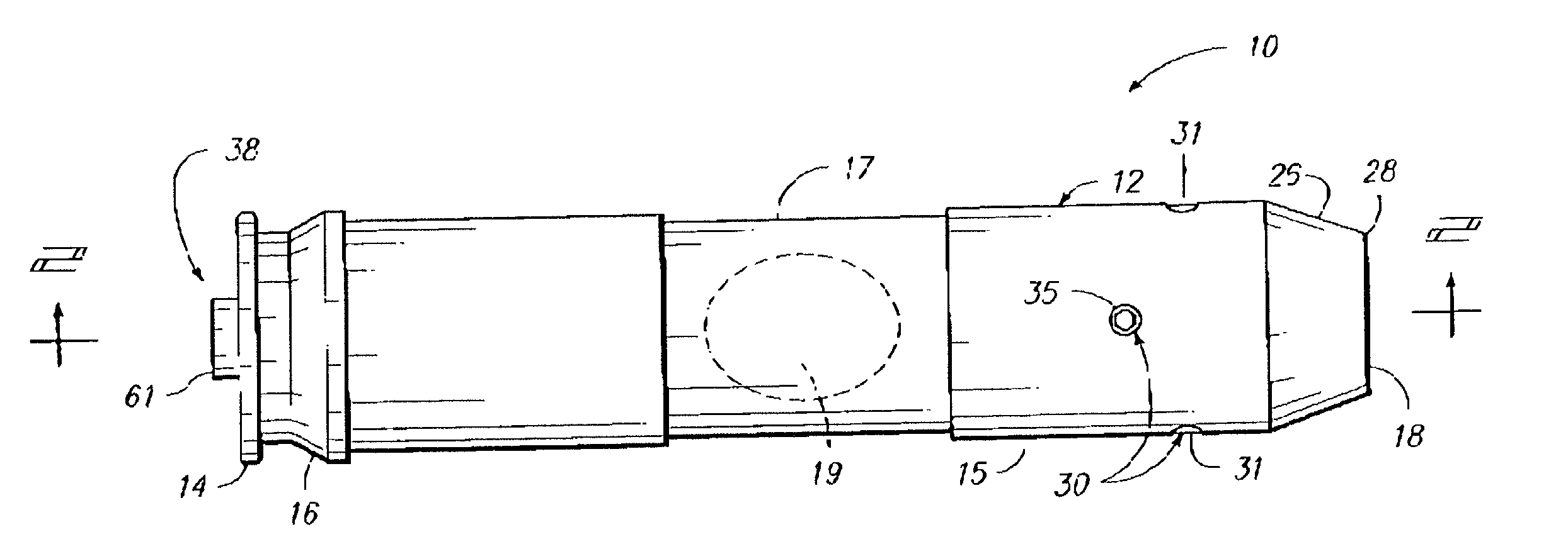
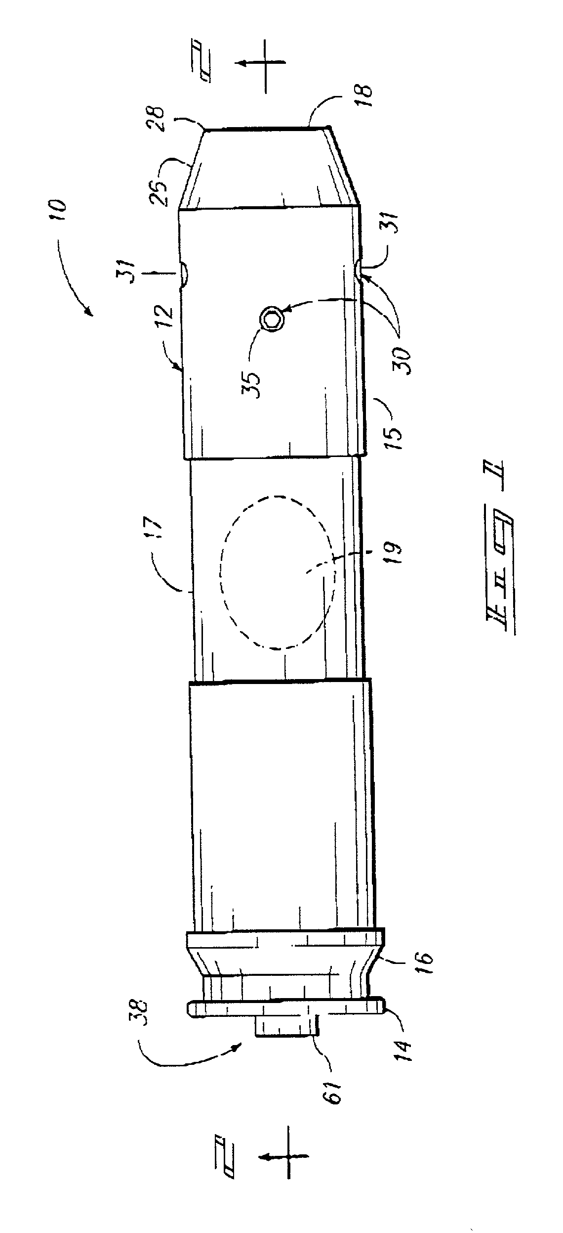
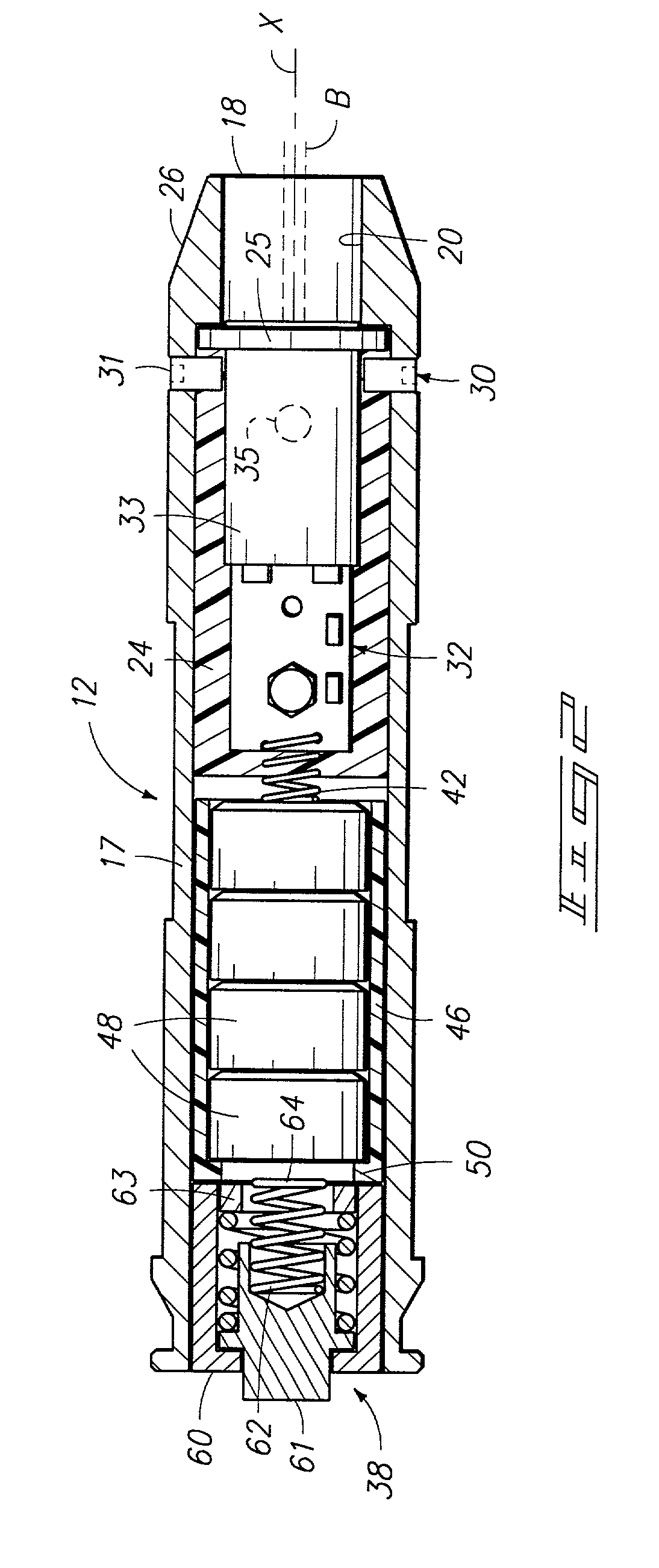
A firearm bore sighting system is described in which conventionally shaped cartridge body with a rim at a base end and an open forward end includes a bore formed along a cartridge axis. An optical beam emitting device is received within the bore, with potting material formed about the beam emitting device, securing the beam emitting device in a spatial relation to the cartridge axis such that an optical beam emitted from the beam emitting device is coaxial with the cartridge axis.

Description

TECHNICAL FIELD[0001] The present invention relates to bore sighting for firearms, and particularly to a device that aids in bore sighting procedures.BACKGROUND OF THE INVENTION[0002] The prior processes involved for "sighting in" a firearm typically involve the use of a target and live ammunition. While this process is typically satisfactory for the shooter, a considerable amount of time and a degree of expense are involved.[0003] The above "sighting in" process may not be available in certain situations. For example, a hunter may jar the firearm and upset the previous sight adjustments. The hunter may be in a situation where the typical process for "sighting in" the weapon is not possible or advisable. This is especially true in situations where the discharge of the firearm could have a negative effect on hunting situations. Further, access to a proper target range is not always easily available. A need has therefore been realized for some form of sighting device that does not req...

Claims


Application Information

Patent Timeline
Patent Type & Authority Applications(United States)
IPC IPC(8): F41A33/02
CPCF41A33/02
Inventor IAFRATE, TERRY A.DAVIS, KELLY J.
Owner HUNT'S
Learn More