Spray cooled motor system

a technology of spray cooling and motor system, which is applied in the direction of windings, magnetic circuit rotating parts, magnetic circuit shape/form/construction, etc., can solve the problems of limited performance of these parts

Inactive Publication Date: 2002-09-19
ISOTHERMAL SYST RES
View PDF5 Cites 31 Cited by
  • Summary
  • Abstract
  • Description
  • Claims
  • Application Information

AI Technical Summary

Problems solved by technology

While motors have been known for years, their performance has been limited by th

Method used


Image

  • Spray cooled motor system
  • Spray cooled motor system
  • Spray cooled motor system

Examples


Embodiment Construction

[0017] Many of the fastening, connection, manufacturing and other means and components utilized in this invention are widely known and used in the field of the invention described, and their exact nature or type is not necessary for an understanding and use of the invention by a person skilled in the art or science; therefore, they will not be discussed in significant detail. Furthermore, the various components shown or described herein for any specific application of this invention can be varied or altered as anticipated by this invention and the practice of a specific application or embodiment of any element may already be widely known or used in the art or by persons skilled in the art or science; therefore, each will not be discussed in significant detail.

[0018] The terms "a", "an", and "the" as used in the claims herein are used in conformance with long-standing claim drafting practice and not in a limiting way. Unless specifically set forth herein, the terms "a", "an", and "th...


PUM


Abstract

A spray cooled motor system with a motor housing with an interior and an exterior, a stator mounted within the interior of the motor housing, a rotor mounted within the interior of the motor housing, a coil winding mounted within the interior of the motor housing, a plurality of atomizers configured to spray a coolant on at least one of the stator and the rotor, a coolant pump in fluid communication with the plurality of atomizers; and an output shaft extending through an output shaft aperture from the interior to the exterior of the motor housing.

Description

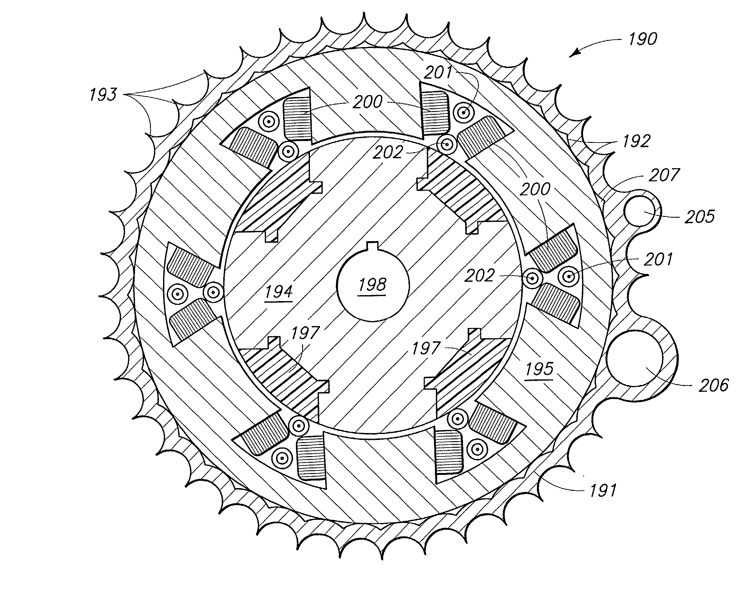
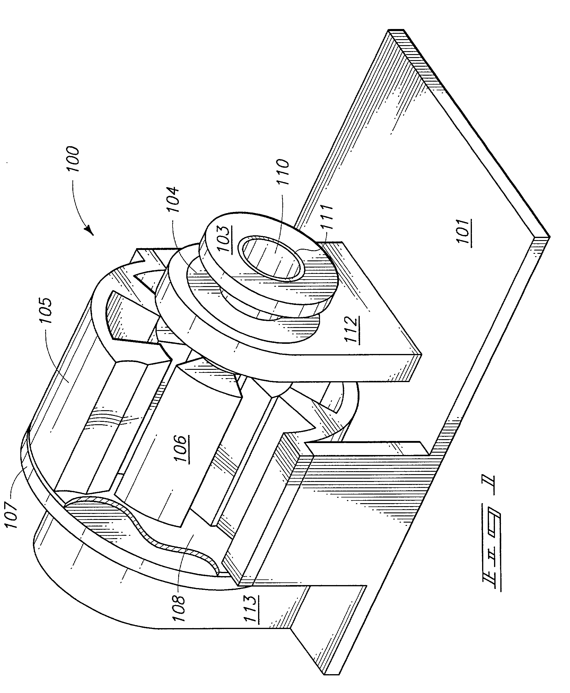
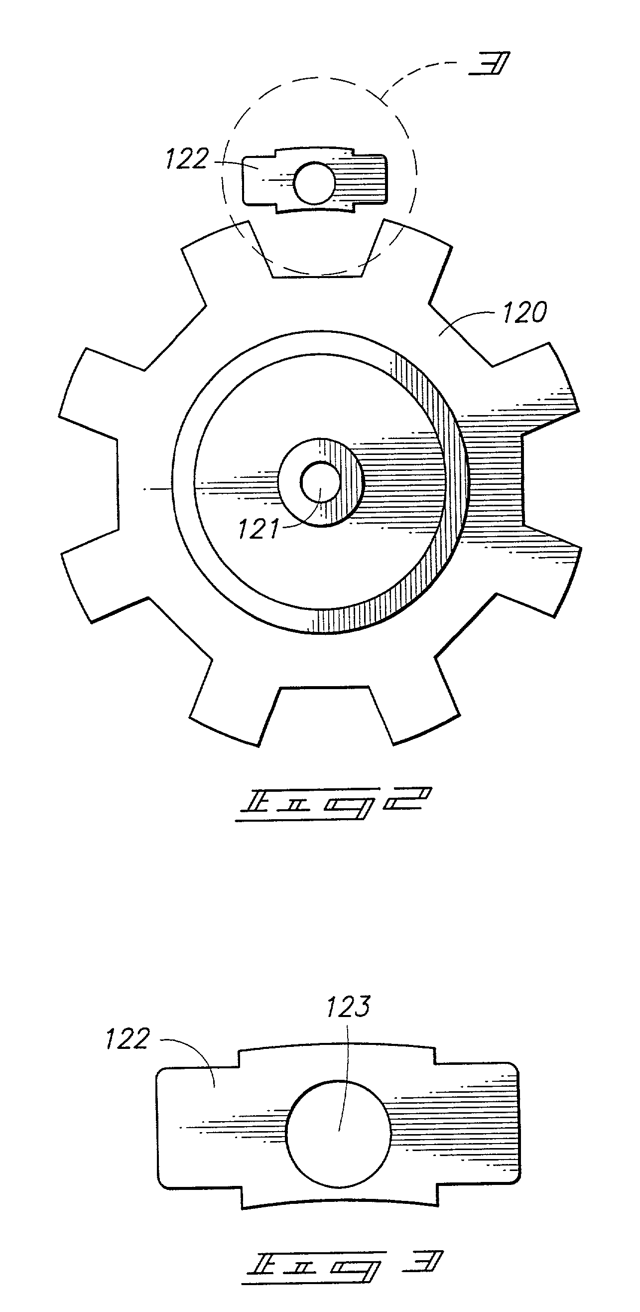
CROSS REFERENCE TO RELATED APPLICATIONS[0001] This application claims priority from U.S. Provisional Application Serial No. 60 / 234,565 filed Sep. 22, 2000, titled "INTEGRATED MOTOR, THERMAL CONTROL AND POWER ELECTRONICS", naming Charles L. Tilton as Inventor, and which is incorporated herein by this reference.TECHNICAL FIELD[0002] This invention generally pertains to a spray cooled motor system.BACKGROUND OF THE INVENTION[0003] While motors have been known for years, their performance has been limited by thermal constraints and their ability to remove heat from part or all of the motor. Improved thermal characteristics and / or enhanced motor operational characteristics may be achieved with internal spray cooling.[0004] It is an object of this invention to provide a spray cooled electric motor system.BRIEF DESCRIPTION OF THE DRAWINGS[0005] Preferred embodiments of the invention are described below with reference to the following accompanying drawings.[0006] FIG. 1 is a perspective vie...

Claims


Application Information

Patent Timeline
IPC IPC(8): H02K5/18H02K5/20H02K9/00H02K9/19H02K9/20H02K11/04
CPCH02K5/18H02K5/20H02K9/19H02K9/20H02K2205/09H02K11/33H02K5/203
Inventor TILTON, CHARLES L.WOS, GEORGE J.BADDELEY, RYAN J.
Owner ISOTHERMAL SYST RES
Why Eureka
Try Eureka