Girinding wheel machine bracket adjustable in angle

a technology of angle adjustment and grinding machine, which is applied in the direction of grinding machine components, grinding machines, manufacturing tools, etc., can solve the problems of greater moment of force exerted on the bolt, failure of grinding operation, and machine operator is not sure of the degree of the angle that has been adjusted

Inactive Publication Date: 2002-12-26
LIN JUNG HUA
View PDF0 Cites 7 Cited by
  • Summary
  • Abstract
  • Description
  • Claims
  • Application Information

AI Technical Summary

Problems solved by technology

As a result, the workpiece is not supported by the bracket 150, thereby resulting in failure of the grinding operation.
The prior art structure is defective in design in that the bracket 150 is apt to sway due to the bolt 190 being separated from the planar surface 153 by a greater distance, thereby resulting in a greater moment of force exerting on the bolt 190.
In addition, the machine operator is not sure of the degree of the angle that has been adjusted.

Method used


Image

  • Girinding wheel machine bracket adjustable in angle
  • Girinding wheel machine bracket adjustable in angle
  • Girinding wheel machine bracket adjustable in angle

Examples


Embodiment Construction

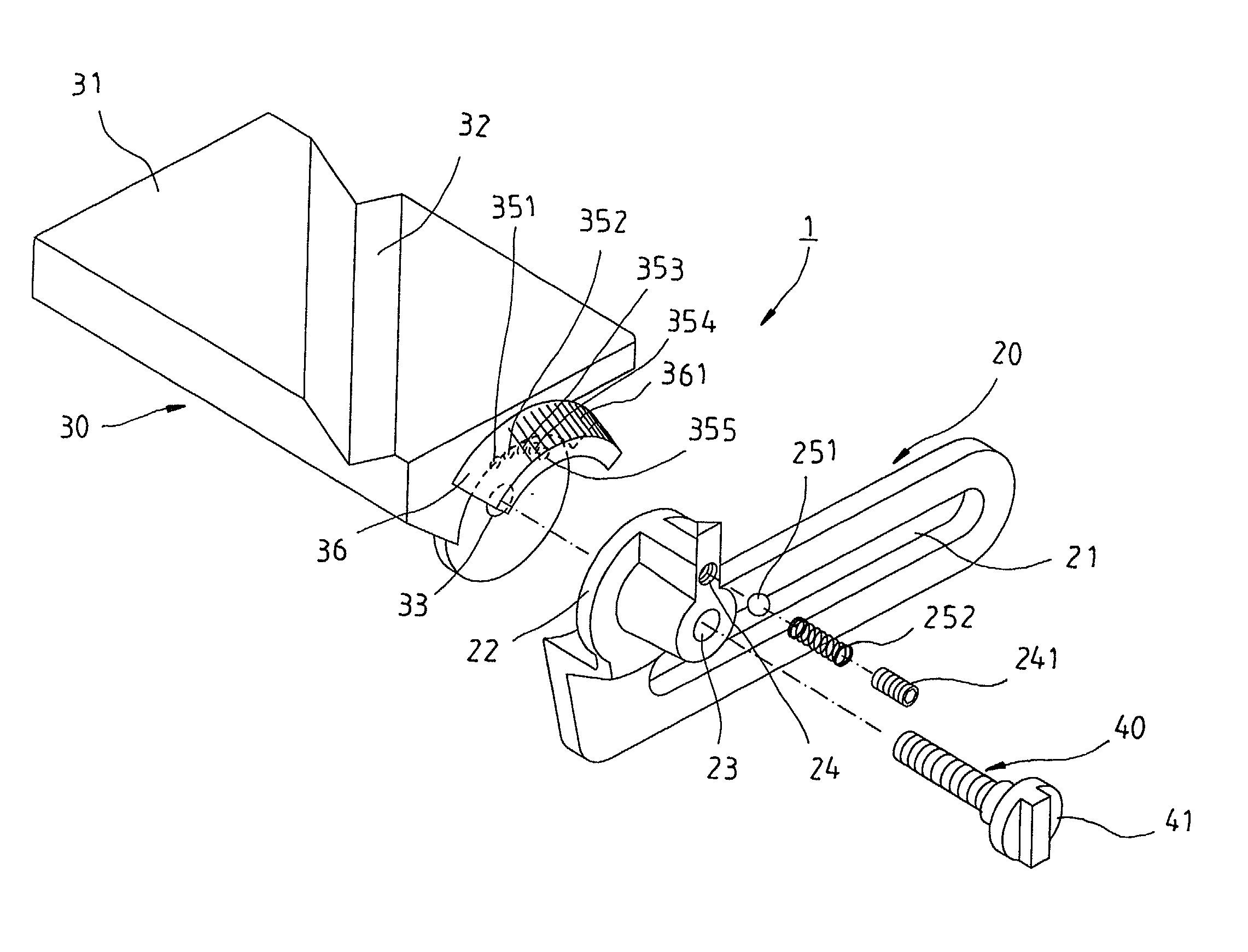
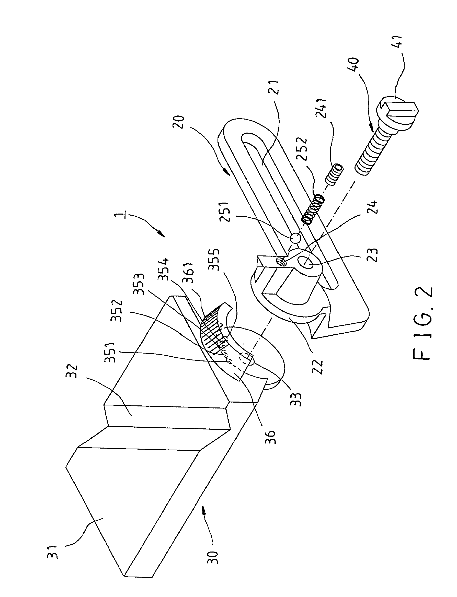
[0013] As shown in FIG. 2, a grinding wheel machine bracket 1 embodied in the present invention comprises the following component parts.

[0014] A fixation seat 20 is a long plate and is provided with a long through hole 21 to receive two bolts 190 by means of which the fixation seat 20 is fixed on the grinding wheel shield 130 of a grinding wheel machine 100, as shown in FIG. 3. The fixation seat 20 is provided in the top in proximity of the front end thereof with a pivoting seat 22 which is provided in the center with an axial hole 23, and a receiving hole 24 which is located over the axial hole 23 and is provided with a metal ball 251 and spring 253, and then a bolt 241 for sealing off the opening of the outer side of the receiving hole 24. The opening of the inner side of the receiving hole has a diameter slightly small than the metal ball 251, thereby enabling the metal ball 251 to be urged by the spring 252 in such a manner that a portion of the metal ball 251 is partially jutte...


PUM


Abstract

A grinding wheel machine bracket comprises a fixations eat having a long through hole to receive a screw for fastening the fixation seat with a grinding wheel machine. The fixation seat has a pivoting seat with an axial hole, and a pointer located at the top thereof. A bracket seat is provided with a loading surface, a threaded hole, and an arcuate shoulder plate located over the threaded hole. A threaded rod is engaged with the threaded hole of the fixation seat via the axial hole. The bracket seat is changed in angle in relation to the fixation seat so as to adjust the angle of the loading surface of the bracket seat in relation to the grinding wheel of the grinding wheel machine. The bracket seat is fixed by the threaded rod at an angle so set.

Description

FIELD OF THE INVENTION[0001] The present invention relates generally to a grinding wheel machine, and more particularly to a grinding wheel machine bracket which is adjustable in angle.BACKGROUND OF THE INVENTION[0002] As shown in FIG. 1, a grinding wheel machine 100 of the prior art comprises a motor 110, a grinding wheel 120 mounted on the output shaft of the motor 110 and driven by the motor 110 to turn. A grinding wheel shield 130 serves to shield the grinding wheel 120. An eye protecting plate 140 is fastened with the grinding wheel shield 130 for protecting the eyes of a machine operator from the flying debris in the course of the grinding operation. A bracket 150 is provided at one end with a fastening portion 151 and a long through hole 152 for receiving two bolts 190 which are used to fix the bracket 150 on the grinding wheel shield 130. The fastening portion 151 is provided at the outer end with a support planar surface 153 corresponding to the peripheral edge of the grind...

Claims


Application Information

Patent Timeline
Patent Type & Authority Applications(United States)
IPC IPC(8): B24B27/02
CPCB24B27/02
Inventor LIN, JUNG-HUA
Owner LIN JUNG HUA
Why Eureka
Try Eureka