Controlling forward link transmission power

a forward link and transmission power technology, applied in power management, radio transmission, electrical equipment, etc., can solve the problems of user terminals experiencing varying levels of interference susceptibility, user terminals being more susceptible to interference from neighboring beams, etc., to maintain interference levels and conserve transmit power

Inactive Publication Date: 2003-05-01
QUALCOMM INC
View PDF0 Cites 38 Cited by
  • Summary
  • Abstract
  • Description
  • Claims
  • Application Information

AI Technical Summary

Benefits of technology

0019] An advantage of the present invention is that it keeps interference levels within acceptable ranges, while conserving transmit power.
0020] The present invention is described with reference to the accompanying drawings. In the drawings, like reference numbers indicate identical or functionally similar elements. Additionally, the left-most digit(s) of a reference number identifies t...

Problems solved by technology

In communications systems employing multiple beams, transmissions received by users in a particular beam are susceptible to interference from transmissions designated for neighboring beams.
In addition, the closer a user is to an adjacent beam, the more susceptible the user is to interference from neighboring beams.
Accordingly, a user terminal may experience varying levels of interference susce...

Method used


Image

  • Controlling forward link transmission power
  • Controlling forward link transmission power
  • Controlling forward link transmission power

Examples


Embodiment Construction

[0027] I. Exemplary Operational Environment

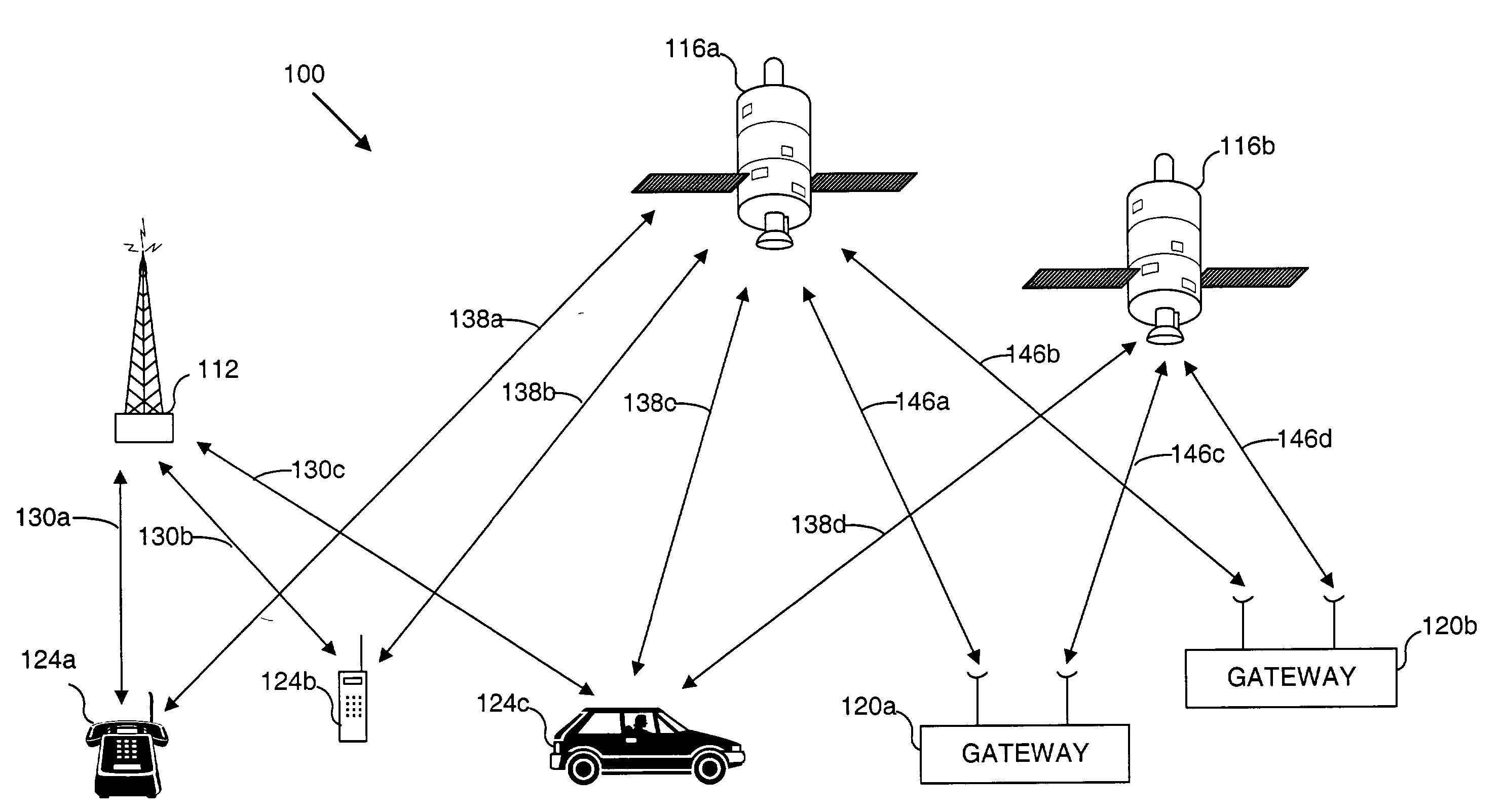
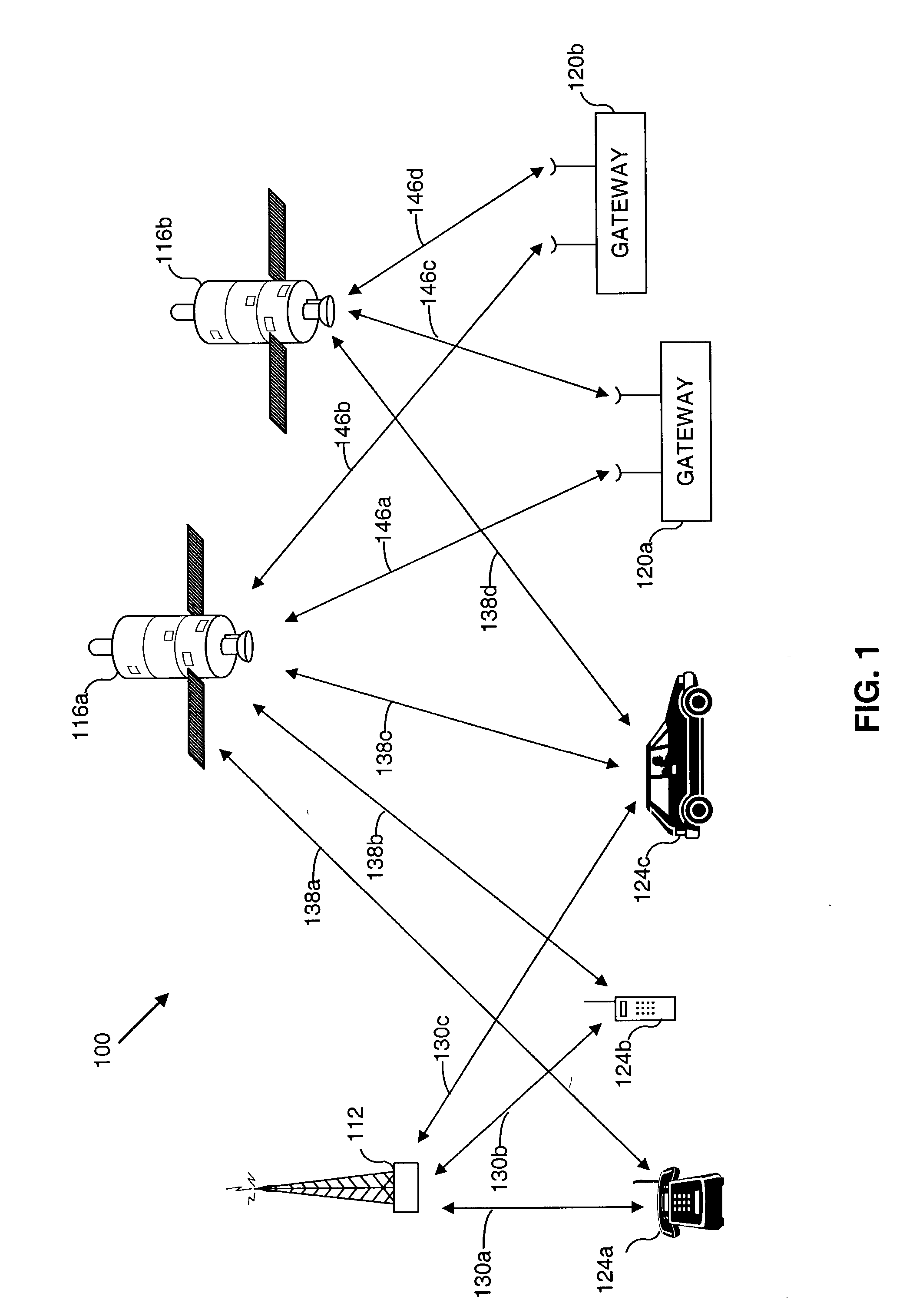
[0028] Before describing the invention in detail, it is helpful to describe an example environment in which the invention may be implemented. The present invention is particularly useful in mobile communications environments. FIG. 1 illustrates such an environment.

[0029] FIG. 1 is a block diagram of an exemplary wireless communication system (WCS) 100 that includes a base station 112, two satellites 116a and 116b, and two associated gateways (also referred to herein as hubs) 120a and 120b. These elements engage in wireless communications with user terminals 124a, 124b, and 124c. Typically, base stations and satellites / gateways are components of distinct terrestrial and satellite based communication systems. However, these distinct systems may interoperate as an overall communications infrastructure.

[0030] Although FIG. 1 illustrates a single base station 112, two satellites 116, and two gateways 120, any number of these elements may be empl...


PUM


Abstract

Forward link transmission power to a user terminal in a wireless communications system having a plurality of beams is controlled by identifying the location of a user terminal within one of the plurality of beams, and setting the forward link transmission power in response to the identified user terminal location. Identifying user terminal location may include receiving from the user terminal multiple signal power measurements, such as pilot signal measurements. From these measurements, a difference is calculated between a first of the signal power measurements that corresponds to a home beam and each of the other signal power measurements. If the largest of the calculated differences is greater than a predetermined threshold, it is concluded that the user terminal is within a beam central region. However, if the largest of the calculated differences is less than or equal to the predetermined threshold, then it is concluded that the user terminal is within a beam crossover region.

Description

[0001] I. Field of the Invention[0002] The present invention generally relates to wireless communications networks. More particularly, the present invention relates to apparatus and method for efficient interference management.[0003] II. Background Art[0004] There are a variety of wireless communication systems having multiple beam communication links. A satellite-based communication system is one such example. Another example is a cellular communication system.[0005] A satellite-based communication system includes one or more satellites to relay communications signals between gateways (also referred to as "communication stations") and user terminals. Gateways provide communication links for connecting a user terminal to other user terminals or users of other communications systems, such as a public switched telephone network. User terminals can be fixed or mobile, such as a mobile telephone, and positioned near a gateway or remotely located.[0006] A satellite can receive signals fr...

Claims


Application Information

Patent Timeline
IPC IPC(8): H04B7/185H04B7/204
CPCH04B7/2041H04B7/18543H04W52/283
Inventor MALLADI, DURGA P.
Owner QUALCOMM INC
Why Eureka
Try Eureka