Structural panels and method of connecting same

a technology of structural panels and accessories, applied in the direction of walls, flooring, building components, etc., can solve the problems of affecting the installation of the required stress, the risk of the lower lip of the groove buckle, and the relative sensitiveness of the known panel core material,

Inactive Publication Date: 2003-06-05
KRONOTEC
View PDF6 Cites 329 Cited by
  • Summary
  • Abstract
  • Description
  • Claims
  • Application Information

AI Technical Summary

Problems solved by technology

However, the core material of known panels is relatively sensitive, which is often not realized, particularly by those engaged in home repair.
If care is not taken when laying the panels and if strong forces are exerted when a new panel is inserted or swung downwards there is the danger that the lower lip of the groove will buckle.
This results in the required stress not being able to be applied to the floor panels during installation since the position of the interlocking mechanism has changed.
Also, if the lower lip buckles too much it is possible that the groove will be broken, a circumstance that cannot be identified from the outside.
If, for example, tool wear results in the projection on the tongue being insufficiently high, the two panels will not lock together in solid fashion, and the danger will arise of the panels separating or of surface gaps forming at the connecting points.
If the projection is too high it will not fit the lower lip of the panel provided with the groove.
The danger may also arise of the lower lip buckling and being broken or the projection being damaged (ground down), making a solid connection of the panels impossible.
Panels that have once been connected can no longer be separated without deliberate mechanical action.

Method used


Image

  • Structural panels and method of connecting same
  • Structural panels and method of connecting same
  • Structural panels and method of connecting same

Examples


Embodiment Construction

[0041] For purposes of clarity, in the embodiments described below the same components or profiles are designated with the same reference numerals and the like.

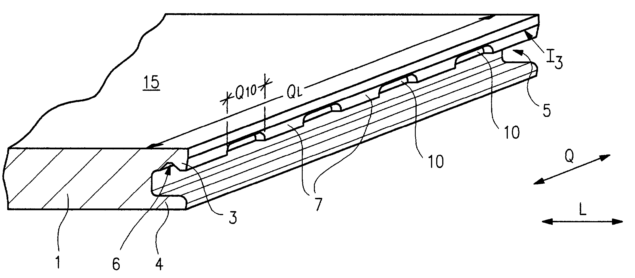
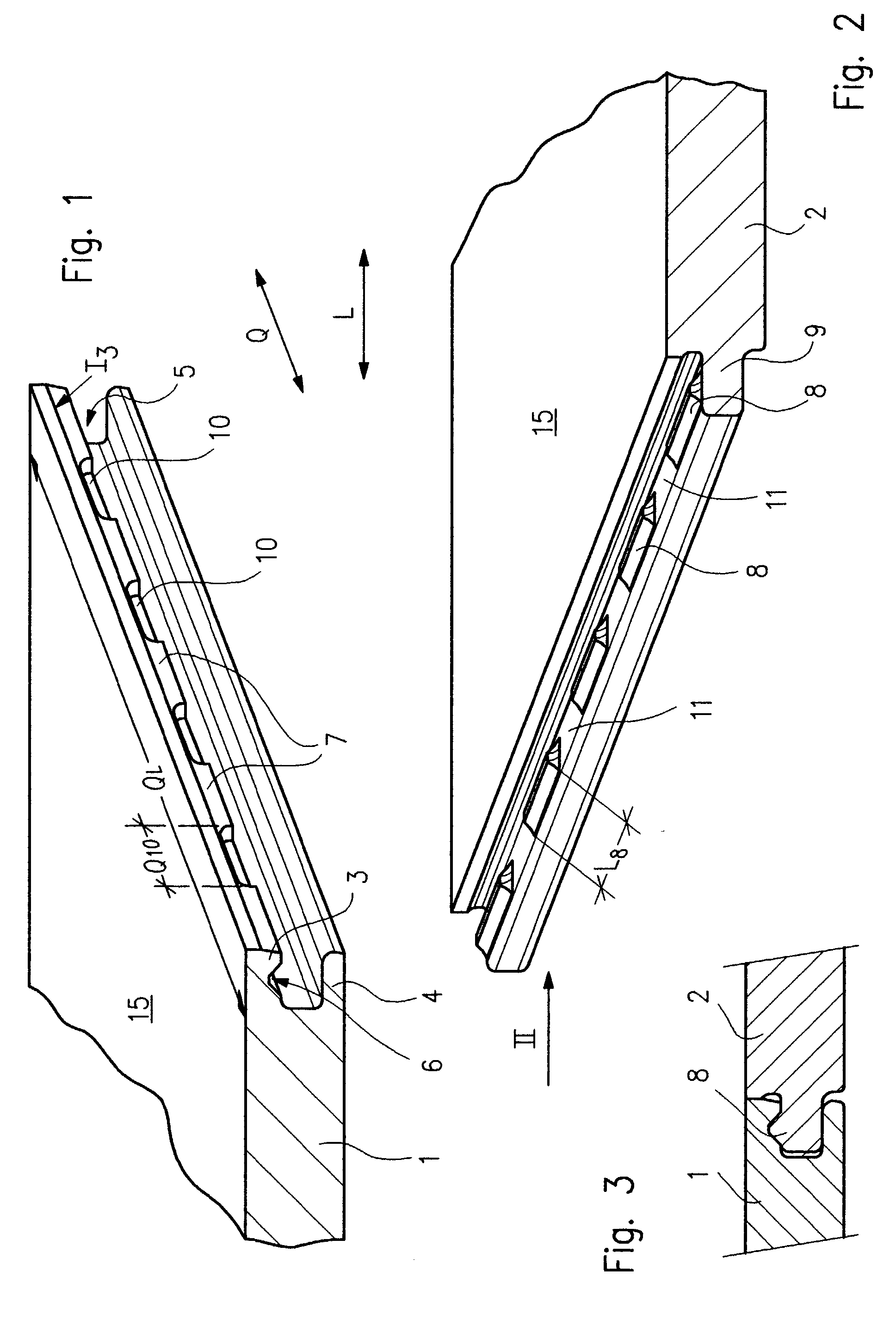
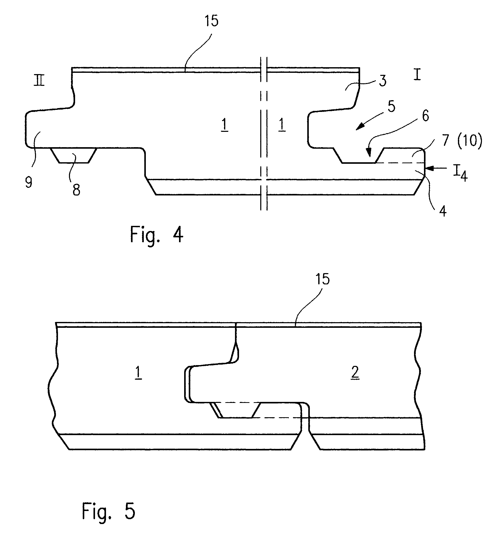
[0042] Referring now to FIGS. 1-3, panels 1, 2 are provided on a traverse side I with a contour in accordance with FIG. 1, 2 or 4 or, alternatively, FIGS. 8 and 9. A contour in accordance with FIG. 10 is, in embodiments, provided on the longitudinal side. In embodiments, the panels 1, 2 consist of a moderately dense or highly compressed fiberboard (MDF or HDF). The structural panels may also consist of a material such as wood, plaster or plastic. The upper surface 16 of the panels 1, 2 are provided with a decorative upper layer 15 which may be formed, e.g., by a paper layer exhibiting a wood grain and coated with a layer of synthetic resin for protection against wear. A soundproofing layer may additionally be glued to the underside 17 in order to improve the acoustic properties of the floor with respect to walking noise. A la...


PUM


Abstract

A device for connecting and locking structural panels, particularly floor panels, having a groove forming an upper lip and a lower lip over the entire length of at least one lateral border and with a tongue formed on the opposite lateral border corresponding to the groove. To lock panels that have been connected, the tongue is provided with at least one projection and the groove exhibits at least one indentation on the lip that faces the projection, which device is characterized by the indentation being longer than the projection, and on its lateral border (I3, I4) the lip provided with at least one indentation exhibits at least one recess reaching back to the indentation. The length of the recess is at least as great as the length of the projection, and seen in the longitudinal direction, the recess and the projection occupy positions that are staggered, one relative to the other.

Description

DESCRIPTION[0001] 1. Field of the Invention[0002] The present invention relates to an apparatus for connecting and locking structural panels, and more particularly to a locking structure of floor panels and a method of locking floor panels using the locking structure.[0003] 2. Background Description[0004] Locking mechanism for floor panels are known, for example, DE 100 08 108. In such floor panels, a groove forms an upper lip and a lower lip over the entire length of at least one lateral border, and a tongue is formed on the opposite lateral border which corresponds to the groove. To lock panels that have been connected, the tongue is provided with at least one projection and the groove exhibits at least one indentation on the lip that faces the projection. The locking mechanism created by the corresponding profiling of the tongue and the groove forms a so-called "click profile". Two panels are connected by inserting the tongue of one panel into the groove of the other panel, until...

Claims


Application Information

Patent Timeline
Patent Type & Authority Applications(United States)
IPC IPC(8): E04F15/02E04F15/04
CPCE04F15/02E04F15/04E04F2201/025E04F2201/0123E04F2201/022E04F2201/0115
Inventor TYCHSEN, DETLEF
Owner KRONOTEC
Why Eureka
Try Eureka