Deck assembly for a self-propelled, walk-behind rotary lawn mower

a self-propelled, rotary lawn mower technology, applied in mowers, agriculture tools and machines, agriculture, etc., can solve the problems of high manufacturing and material costs of high-sloped decks, sloped decks often require mulch plugs, and the average height of front wheel drive mowers is usually unacceptably high

Inactive Publication Date: 2003-10-02
TORO CO THE
View PDF2 Cites 57 Cited by
  • Summary
  • Abstract
  • Description
  • Claims
  • Application Information

AI Technical Summary

Problems solved by technology

While adequate for rear wheel drive configurations, this elevation is usually unacceptably high for front wheel drive mowers.
While effective, the manufacturing and material costs associated with these highly sloped decks are ge

Method used


Image

  • Deck assembly for a self-propelled, walk-behind rotary lawn mower
  • Deck assembly for a self-propelled, walk-behind rotary lawn mower
  • Deck assembly for a self-propelled, walk-behind rotary lawn mower

Examples


Embodiment Construction

[0028] In the following detailed description of the embodiments, reference is made to the accompanying drawings which form a part hereof, and in which are shown by way of illustration specific embodiments in which the invention may be practiced. It is to be understood that other embodiments may be utilized and structural changes may be made without departing from the scope of the present invention.

[0029] Certain details of the mower may be excluded from the following description and, more particularly, from the accompanying figures, especially where the details are either unnecessary to an understanding of the invention or are otherwise generally known to those of skill in the art.

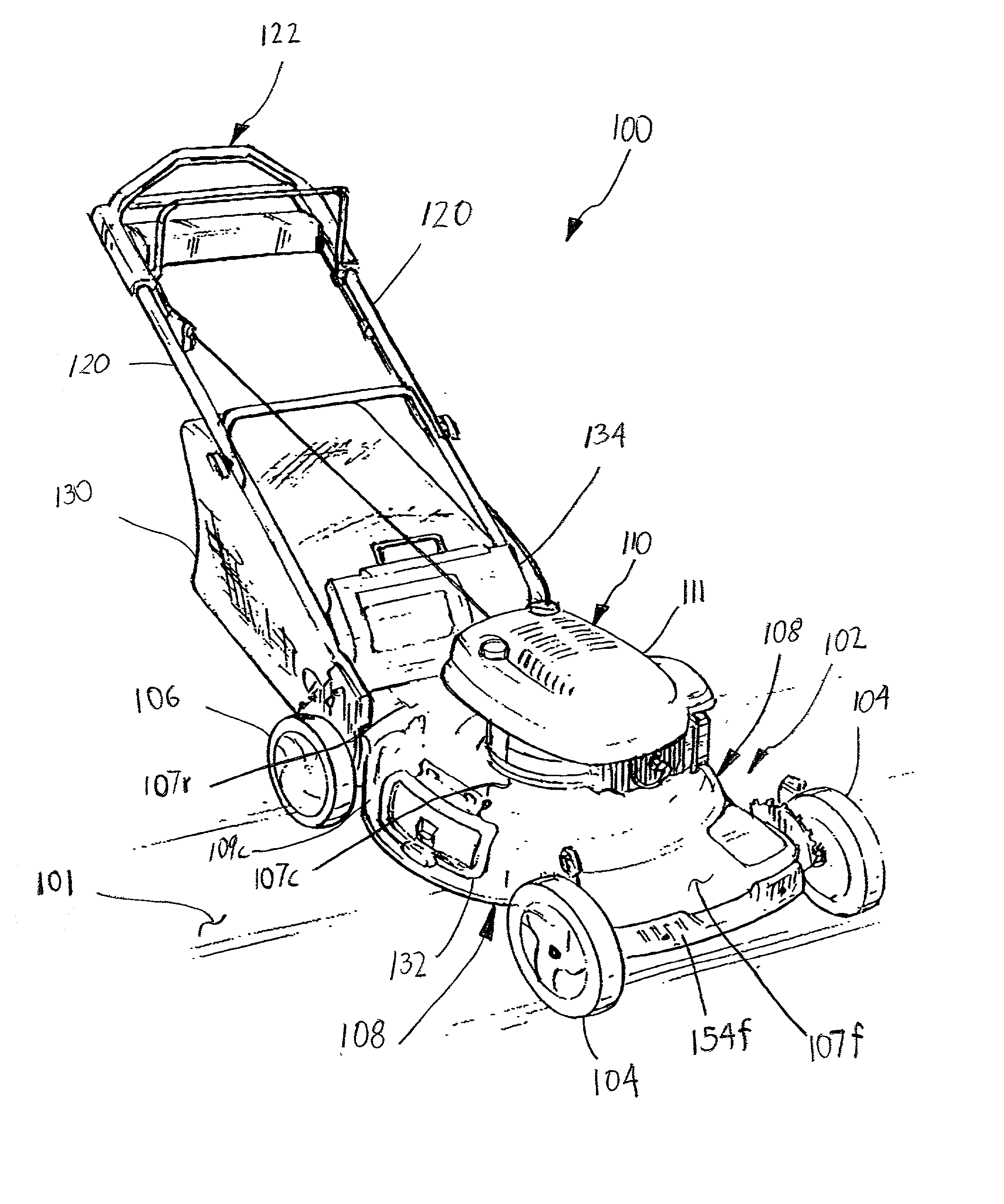
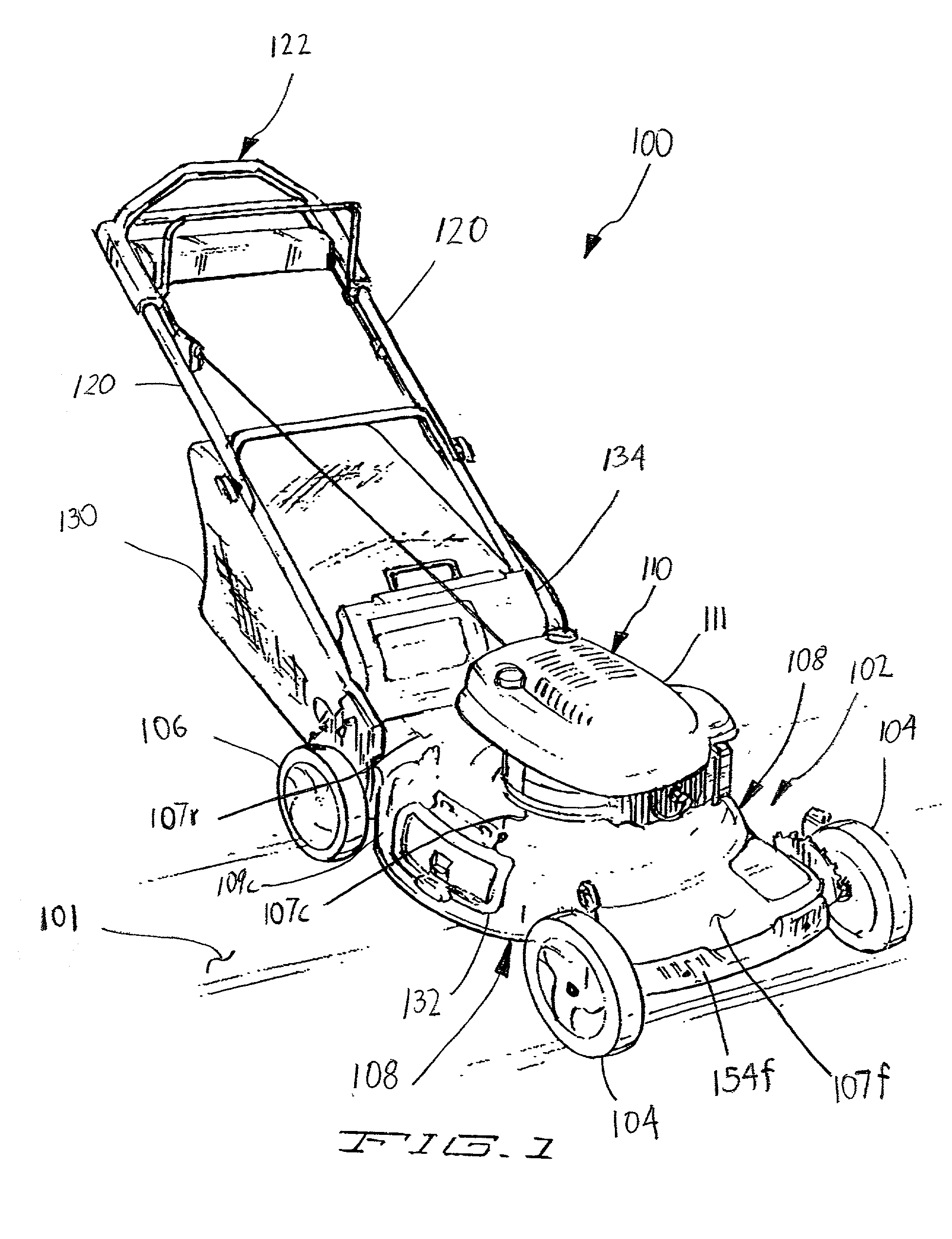
[0030] FIG. 1 illustrates a walk-behind rotary lawn mower 100 in accordance with an exemplary embodiment of the present invention. Preferably, the mower 100 is self-propelled in that one or more wheels are powered as further explained below.

[0031] The mower 100 preferably includes a housing or deck assembl...


PUM


Abstract

A deck assembly for a self-propelled, walk-behind rotary lawn rotary mower is provided. The deck assembly is configurable for either front or rear wheel drive and includes a deck defining a cutting chamber which may house a cutting member. The cutting chamber is bound at least in part by a rear enclosure member. The deck assembly also includes a side discharge port having a side discharge port door. A rear discharge port located on a rear portion of the deck is also provided. Preferably, a duct of substantially rectangular cross section extends through the rear enclosure member between the cutting chamber and the rear discharge port. In one embodiment, the duct has a first, uppermost surface and a second, lowermost surface, wherein the first, uppermost surface and the second, lowermost surface both form substantially horizontal planes.

Description

[0001] The present invention relates to walk-behind rotary lawn mowers. More particularly, the present invention relates to deck assemblies for use with self-propelled, walk-behind rotary lawn mowers.[0002] Conventional walk-behind, rotary lawn mowers typically include a mower deck or housing supported by multiple, e.g., four, wheels. The top side of the deck forms an engine mounting surface to receive a prime mover (e.g., an internal combustion engine or an electric motor) while the underside of the deck forms a cutting chamber operable to house a cutting element, e.g., a cutting blade. The cutting blade is typically attached to a lower end of a vertical drive shaft, e.g., the engine crankshaft, which extends downwardly through the mower deck and into the cutting chamber. During operation, the crankshaft rotates the cutting blade at a speed sufficient to sever grass and other vegetation passing beneath the mower.[0003] While some decks are designed solely for mulching, the deck is ...

Claims


Application Information

Patent Timeline
IPC IPC(8): A01D34/71A01D34/81
CPCA01D34/71A01D2101/00A01D34/81
Inventor BAUMANN, JAMES R.SHAFFER, CHADWICK A.WADZINSKI, CHRIS A.
Owner TORO CO THE
Why Eureka
Try Eureka