Bumper system with face-mounted energy absorber

a technology of energy absorption and bumper system, which is applied in the direction of bumpers, vehicle components, vehicular safety arrangements, etc., can solve the problems of inconsistent collapse of the bumper system, unfavorable vehicle safety, and unfavorable vehicle safety, so as to reduce damage to the vehicle, prevent the condition of die lock, and facilitate tooling

Inactive Publication Date: 2003-10-09
NETSHAPE INT LLC
View PDF14 Cites 29 Cited by
  • Summary
  • Abstract
  • Description
  • Claims
  • Application Information

AI Technical Summary

Benefits of technology

0044] The illustrated box-shaped sections 117-120 are connected together by interconnecting "honeycomb-shaped" structures in the form of four horizontal ribs 160-163 (FIG. 12A) that are spaced equally apart in a vertical direction. It is contemplated that the box-shaped sections 117-120 can be connected together by different arrangements and still incorporate many of the advantages of the present energy absorber. The top rib 160 and the bottom rib 163 extend continuously from end to end of the energy absorber 102. The middle two ribs 161 and 162 also extend end to end of the energy absorber 102, with the exception that the middle ribs 161 and 162 are discontinued near the centerline 115 and do not connect the two center box-shaped sections 117. Also, the ribs 161 and 162 connect the top and bottom legs of the C-shaped inner portion of walls 125 and 134. The box-shaped sections 117-120 are also connected together by a rear wall 164. The rear wall 164 completely covers a rear of the energy absorber 102, with the exception that an opening is formed in the rear wall 164 at each of the box-shaped sections 117-120 to facilitate tooling and prevent a die lock condition. The rear wall 164 not only ties the sections 117-120 together, but also forms vertical straps that tie the top and bottom walls together to prevent the top and bottom walls from spreading apart during an impact. This also eliminates the need for top and bottom fasteners.
0045] A top flange 170 (FIG. 13) and a bottom flange 171 (FIG. 14) are formed on top and bottom edges of the rear wall 164. The flanges 170 and 171 wrap onto tops and bottoms of the bumper beam 101. Fingertip-like pads 172 are formed on the flanges 170 and 171 for engaging mating areas on the top surface and on the bottom surface of the bumper beam 101 to temporarily frictionally retain the energy absorber 102 on the bumper beam 101. Also, hooks 173 (FIGS. 10-11) are formed on tabs that extend from (and co-planar with) the top and bottom walls 122, 123, 132, 133, 142, 143, 152, and 153. The hooks 173 are shaped to engage mating holes in a front face of the bumper beam 101. The hooks 173 (and also flanges 53-54) provide an opportunity for "blind" snap-attachment, such as when an operator has preassembled an energy absorber to a fascia, and then attaches the assembled absorber/fascia as a unit to a vehicle front. In such event, the fascia prevents the operator from attaching the absorber to a bumper beam.
0046] The energy absorber 102 (FIG. 11) includes integrally-formed end sections 180 and 181 that are symmetrically shaped and that are optimally shaped to form end-located crush boxes for energy absorption upon corner impact to a vehicle. The end sections 180 and 181 each include a vertical rib 182 (FIG. 12A) that transversely crosses and connects to the horizontal ribs 160-163 to form a honeycomb shape. The outboard sidewall 155 is extended rearwardly so that it substantially covers the open end of the tube sections on the bumper beam 101. Also, the rear wall 164 is extended at a location 164' (FIGS. 22, 24, and 25) from the outboard sidewall 155 to form a rearwardly extending box 164" (FIG. 25) that fits adjacent an end of the bumper beam. It is noted that the mounting brackets 107 and 108 can include a forward loop 111 that holds the box 164" in place against an end of the bumper beam, if desired. A crescent-shaped flange 183 extends ...

Problems solved by technology

This is disadvantageous since mechanical fasteners require manual labor to install, which can add undesirably to cost.
Also, the mechanical fasteners can result in localized and non-uniform stress distribution during impact, resulting in inconsistent collapse of the bumper system and poor energy absorption on impact.
Further, fixing the energy absorber to the beams results in an inability of the energy absorber to shift and adjust to non-perpendicular and uneven loads transmitted from the impacting bodies.
At the same time, depending on the bumper system, ...

Method used


Image

  • Bumper system with face-mounted energy absorber
  • Bumper system with face-mounted energy absorber
  • Bumper system with face-mounted energy absorber

Examples


Embodiment Construction

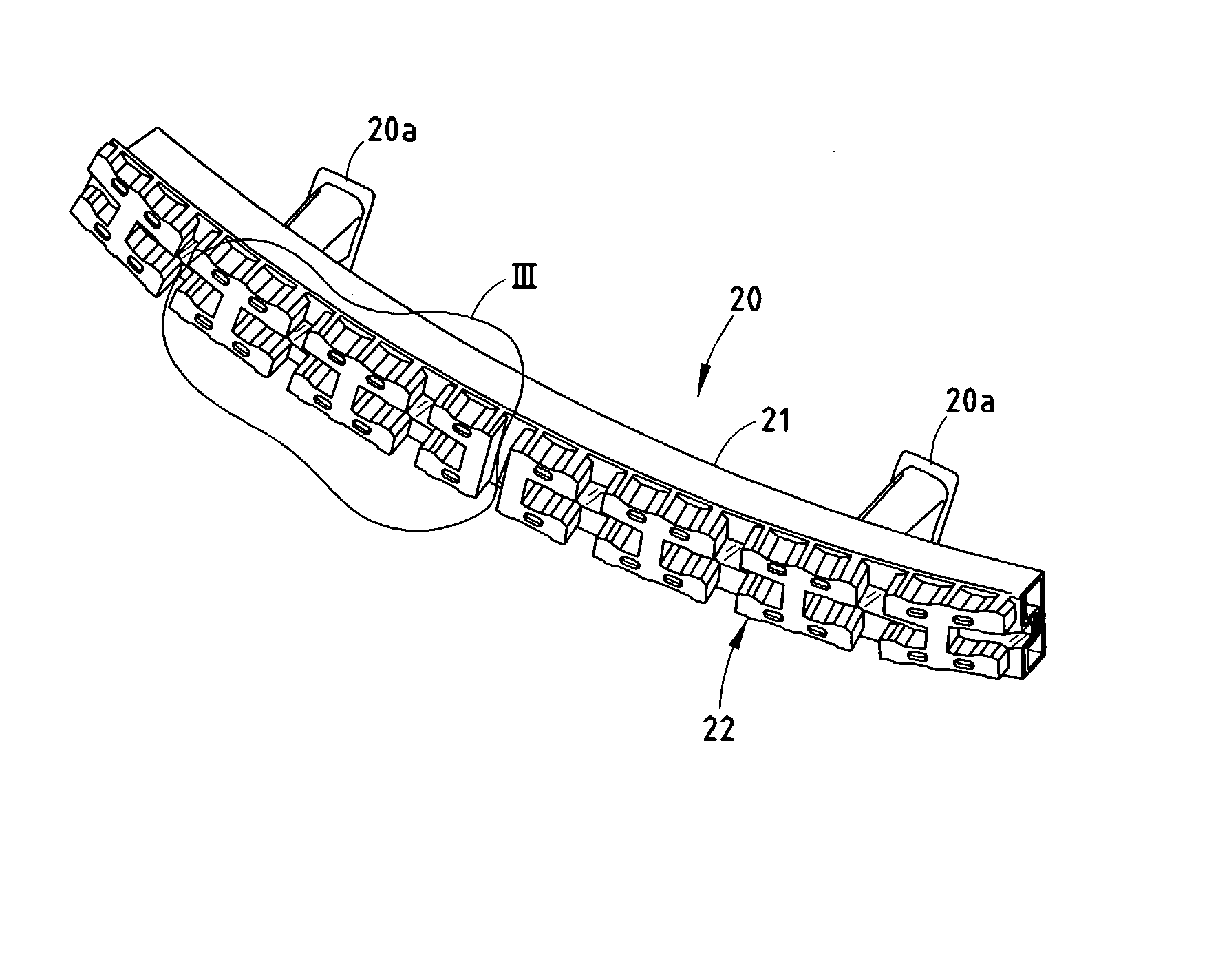
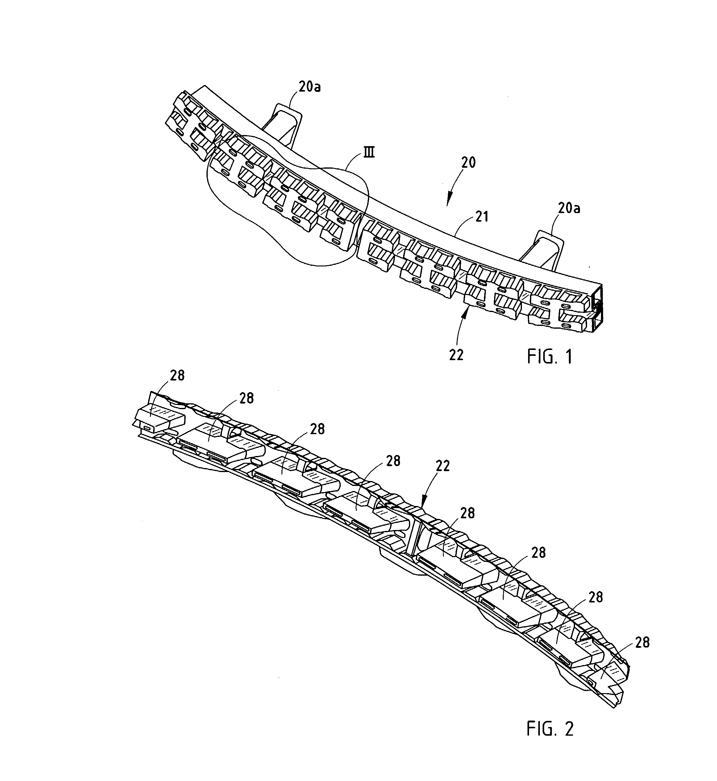
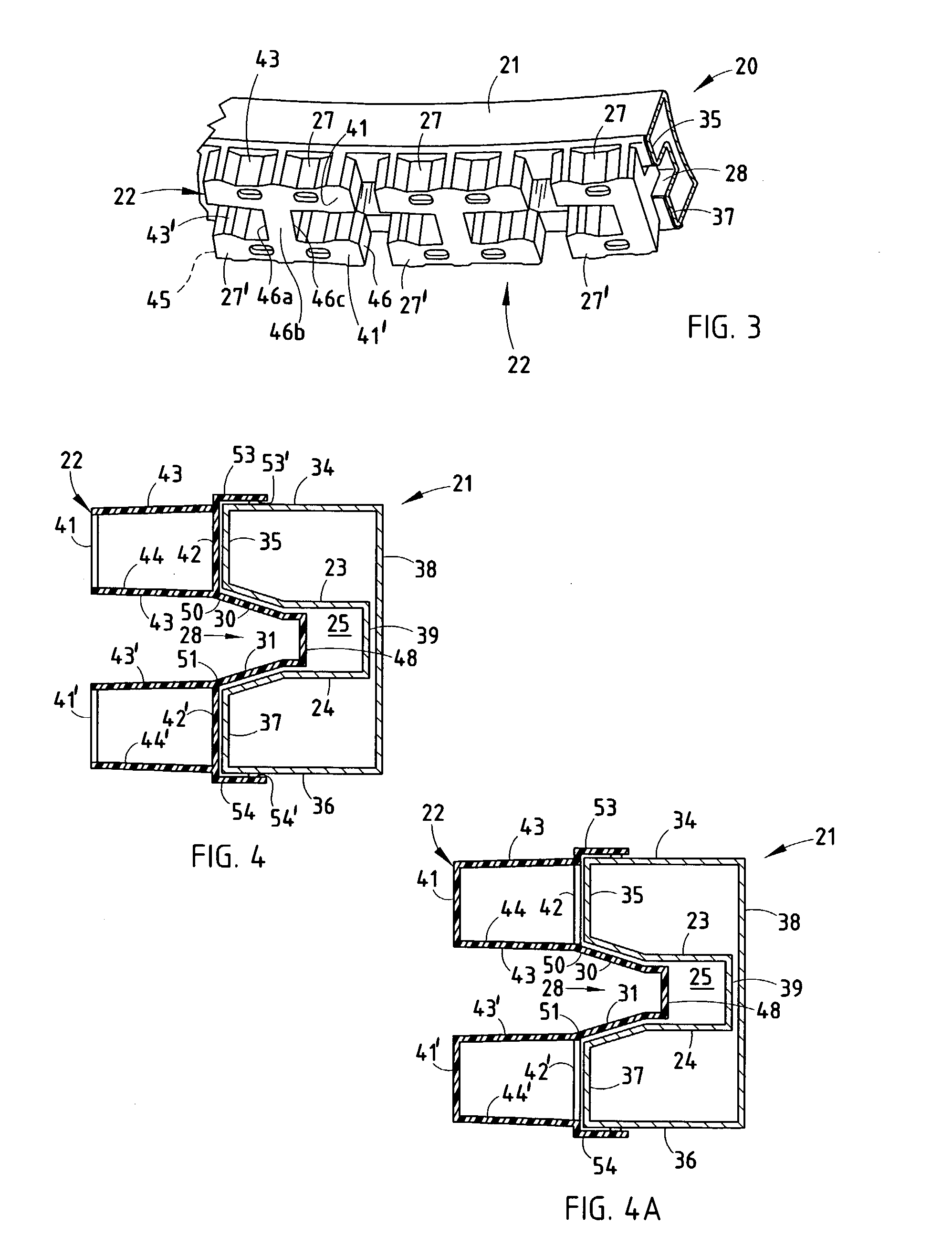
[0051] In regard to the illustrated preferred embodiment, a bumper system 320 (FIGS. 26-31) for vehicles includes a bumper beam 321 and an energy absorber 322 attached to a face of the bumper beam 321. The illustrated beam is rollformed and swept (see Sturrus U.S. Pat. No. 5,454,504) and has a continuous B-shaped double-tubular cross section (FIG. 27). The double tubes are spaced vertically apart and include top and bottom mid-walls 323 and 324 defining a longitudinally-extending channel 325 along its rear surface. A polymeric energy absorber 322 has a length with multiple box-shaped sections 327 (five box-shaped sections are shown, but not all are the same length) that abut the front surface 326 of the bumper beam 321. The energy absorber 322 further includes a plurality of tying sections 328 that extend longitudinally between the box-shaped sections 327 and also vertically between top and bottom portions 327 and 327" of the box-shaped sections 327, as discussed below.

[0052] The B-...


PUM


Abstract

A bumper includes a beam and an energy absorber supported thereon. The energy absorber includes horizontal walls, each having a front portion, a rear portion, and an interconnecting mid-portion that offsets and misaligns the front and rear portions. Upon impact, the front and rear portions collapse with the offset mid portion wrapping back upon itself with a predictable energy-absorbing collapse. The energy absorber further includes flanges and friction pads that frictionally engage the top and bottom of the beam to temporarily retain the energy absorber to the beam. In one embodiment, the front beam wall includes at least one aperture, and the energy absorber includes a tubular column extending from its front wall through the aperture in the front beam wall to the rear beam wall. By this arrangement, the front wall of the energy absorber receives support from the front beam wall via the structural column.

Description

[0001] This application is a continuation-in-part of application Ser. No. 10 / 061,670, filed Feb. 1, 2002, entitled BUMPER SYSTEM WITH FACE-MOUNTED ENERGY ABSORBER, which in turn claims benefit under 35 U.S.C. 119(e) of a provisional application Serial No. 60 / 283,969, filed Apr. 16, 2001, entitled BUMPER SYSTEM WITH FACE-MOUNTED ENERGY ABSORBER. This application is further a continuation-in-part of application Ser. No. 09 / 967,196, filed Sep. 28, 2001, entitled BUMPER SYSTEM WITH FACE-ABUTTING ENERGY ABSORBER, which in turn claims benefit of provisional application Serial No. 60 / 284,058, filed Apr. 16, 2001, entitled BUMPER SYSTEM WITH FACE-ABUTTING ENERGY ABSORBER under 35 USC .sctn.119.BACKGROUND OF THE PRESENT INVENTION[0002] The present invention relates to automotive bumper systems having beams and energy absorbers located on faces of the beams.[0003] Many vehicle designs use energy absorbers positioned on a face or front surface of a steel bumper beam to improve energy absorptio...

Claims


Application Information

Patent Timeline
IPC IPC(8): B60R19/18
CPCB60R19/18B60R2019/1866B60R2019/1813
Inventor EVANS, DARINWEISSENBORN, MARK
Owner NETSHAPE INT LLC
Why Eureka
Try Eureka