Electrical connector

a technology of electrical connectors and connectors, applied in the direction of fixed connections, coupling device connections, coupling protective earth/shielding arrangements, etc., can solve the problems of unsteady terminal position, add the difficulty of manufacturing the insulating housing, etc., and achieve the effect of convenient tooling and uniform pressur

Inactive Publication Date: 2010-08-03
CHENG UEI PRECISION IND CO LTD
View PDF4 Cites 0 Cited by
  • Summary
  • Abstract
  • Description
  • Claims
  • Application Information

AI Technical Summary

Benefits of technology

[0006]An object of the present invention is to provide an electrical connector capable of being assembled easily. The electrical connector includes an insulating housing, a plurality of terminals fixed in the insulating housing and a shell mated with the insulating housing. The insulating housing has a base portion and a mating portion extending from a front surface of the base portion. The mating portion defines a plurality of terminal grooves penetrating through a rear surface of the base portion. The base portion defines a receiving trough communicating rear ends of the terminal grooves and outside of the base portion. Each terminal has a fixed portion received in the corresponding terminal groove and two shoulder portions respectively projecting sideward from two opposite sides of one end of the fixed portion. When the terminals are assembled to the insulating housing, a tool is used to push the shoulder portions to insert the terminals into the corresponding terminal grooves and then the shoulder portions are received in the receiving trough.
[0007]As described above, by disposing the receiving trough communicating the rear ends of the terminal grooves to receive the shoulder portions of the terminals, the shoulder portions can be changed wider to facilitate the tool to provide a uniform pressure to push the terminals enter the terminal grooves during the terminals being assembled to the insulating housing. Thus, the terminals are assembled to the insulating housing more conveniently and rapidly and fixed in the terminal grooves more firmly.

Problems solved by technology

So an interval between two neighboring terminal grooves became narrower, and more obviously to two adjacent containing cavities, this will add the difficulty in manufacturing the insulating housing.
Besides, during using a tool to push the shoulder portions of the terminal to insert the terminal into the terminal groove, it is easy to cause an unsteady location of the terminal because the shoulder portions are not enough wide and the tool can not provide an even force to the shoulder portions.

Method used


Image

  • Electrical connector
  • Electrical connector
  • Electrical connector

Examples


Embodiment Construction

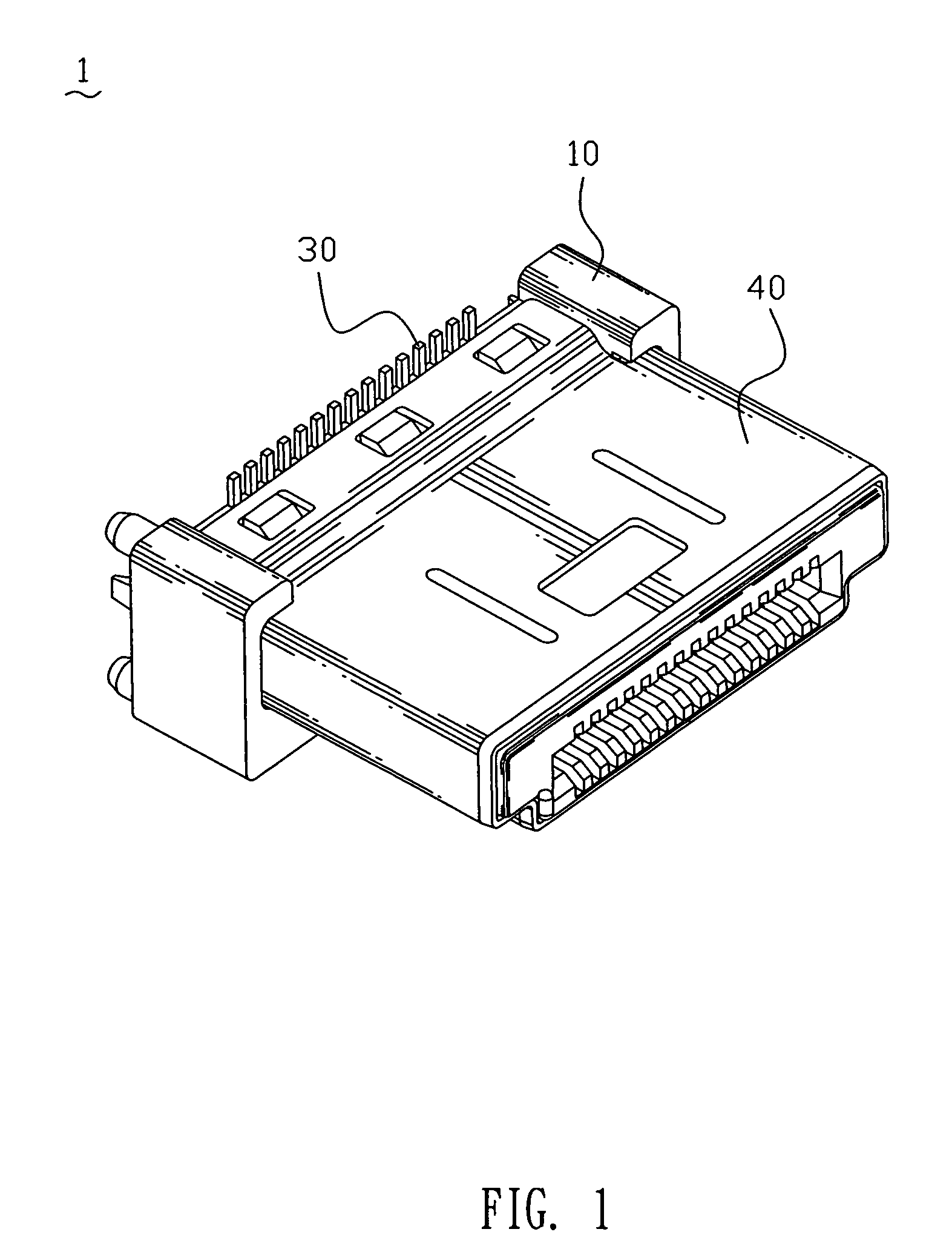
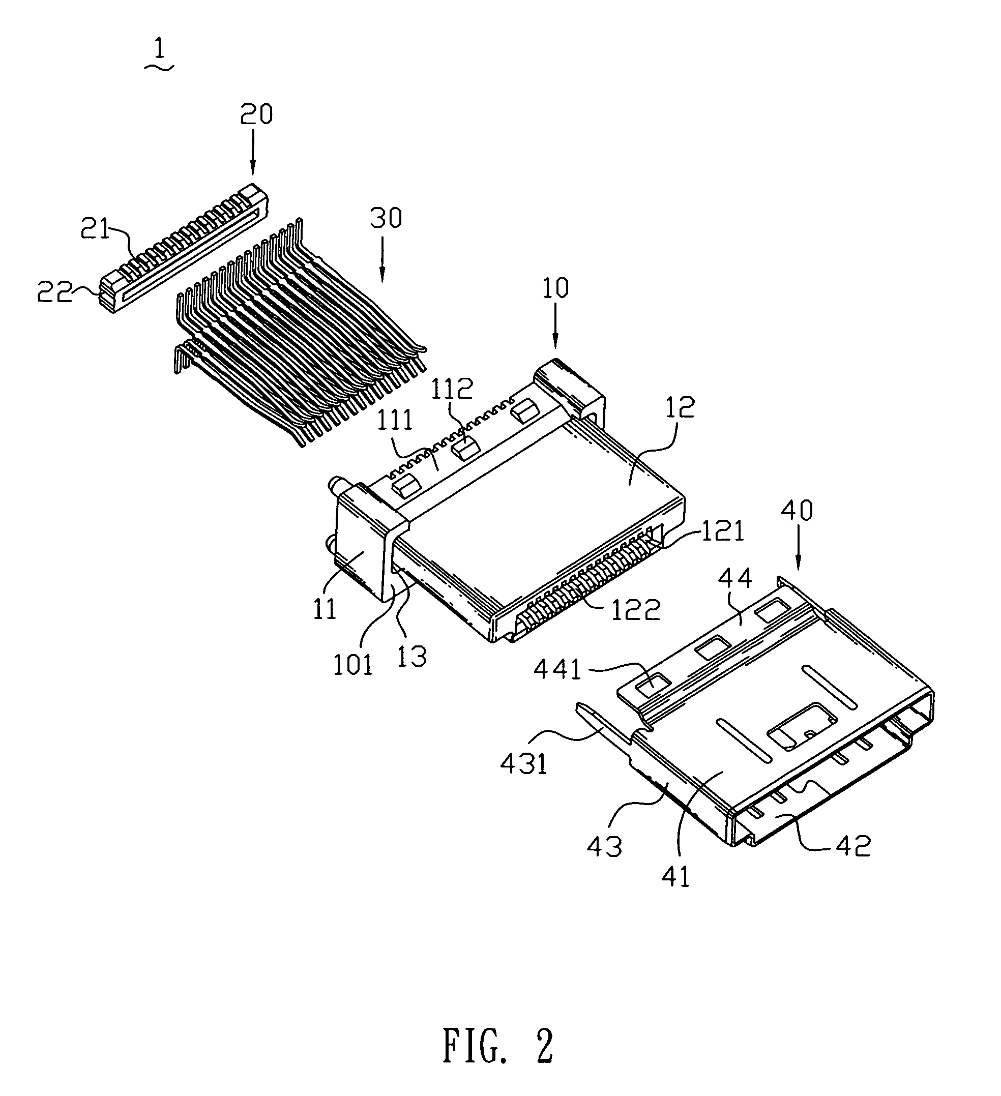
[0018]With reference to FIGS. 1 to 3, an electrical connector 1 according to the invention includes an insulating housing 10, a holding cover 20, a plurality of terminals 30 and a shell 40.

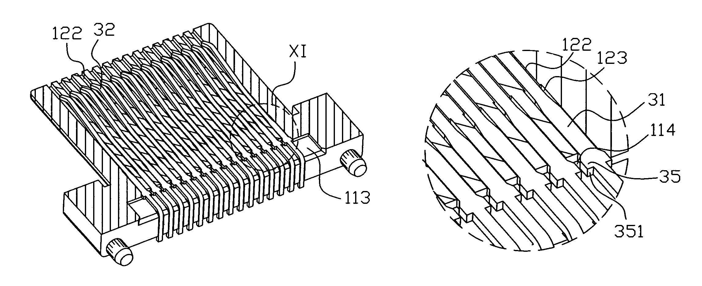
[0019]The insulating housing 10 has a substantially rectangular base portion 11 which defines a front surface 101 and a rear surface 102 (see FIG. 4) opposite to the front surface 101. A mating portion 12 extends from the front surface 101 of the base portion 11. A substantially annular receiving cavity 13 is formed in the front surface 101 of the base portion 11 to around the mating portion 12 for allowing the shell 40 to be partly inserted thereinto. The base portion 11 defines two through slots 116 (as shown in FIG. 4) penetrating therethrough and two insertion cavities (not labeled) in the receiving cavity 13. The two through-slots 116 are respectively adjacent to two opposite sides of the mating portion 12 and the insertion cavities are positioned below the mating portion 12. The mating porti...


PUM


Abstract

An electrical connector includes an insulating housing, a plurality of terminals fixed in the insulating housing and a shell mated with the insulating housing. The insulating housing has a base portion and a mating portion extending from a front surface of the base portion. The mating portion defines a plurality of terminal grooves penetrating through a rear surface of the base portion. Each terminal has a fixed portion received in the corresponding terminal groove and two shoulder portions respectively projecting sideward from two opposite sides of one end of the fixed portion. The base portion defines a receiving trough communicate rear ends of the terminal grooves and outside of the base portion for receiving the shoulder portions. Thus, the terminals can be assembled to the insulating housing conveniently and rapidly during using a tool to push the shoulder portions to insert the terminals into the terminal grooves.

Description

BACKGROUND OF THE INVENTION[0001]1. Field of the Invention[0002]The present invention relates to an electrical connector, and more particularly to an electrical connector capable of being assembled easily.[0003]2. The Related Art[0004]Conventionally, a known electrical connector includes an insulating housing defining a plurality of terminal grooves each of which has a terminal fixed therein. The terminal has a fixed portion, one end of the fixed portion defines an elastic contacting portion and the other end has a welded portion extending therefrom and two shoulder portions respectively projecting outward from two opposite sides thereof. Two opposing sides of one end of the terminal groove respectively extend sideward to form a containing cavity for receiving the shoulder portions therein.[0005]However, considering the miniaturization trend of the electrical connector or an increase in the amount of the terminals, the amount of the terminal grooves should also be increased to corre...

Claims


Application Information

Patent Timeline
Patent Type & Authority Patents(United States)
IPC IPC(8): H01R24/00
CPCH01R13/4367H01R12/57H01R13/506H01R23/6873H01R13/6581
Inventor HO, HSIN-TSUNG
Owner CHENG UEI PRECISION IND CO LTD
Why Eureka
Try Eureka