Link mechanism of reciprocating internal combustion engine

a technology of internal combustion engine and link mechanism, which is applied in the direction of combustion engine, belt/chain/gearing, etc., can solve the problems of deteriorating the durability of the piston skir

Inactive Publication Date: 2003-11-13
NISSAN MOTOR CO LTD
View PDF8 Cites 10 Cited by
  • Summary
  • Abstract
  • Description
  • Claims
  • Application Information

AI Technical Summary

Problems solved by technology

Moreover, the above increase in the thrust load may cause deteriorated durability of a piston skirt 51.

Method used


Image

  • Link mechanism of reciprocating internal combustion engine
  • Link mechanism of reciprocating internal combustion engine
  • Link mechanism of reciprocating internal combustion engine

Examples


first embodiment

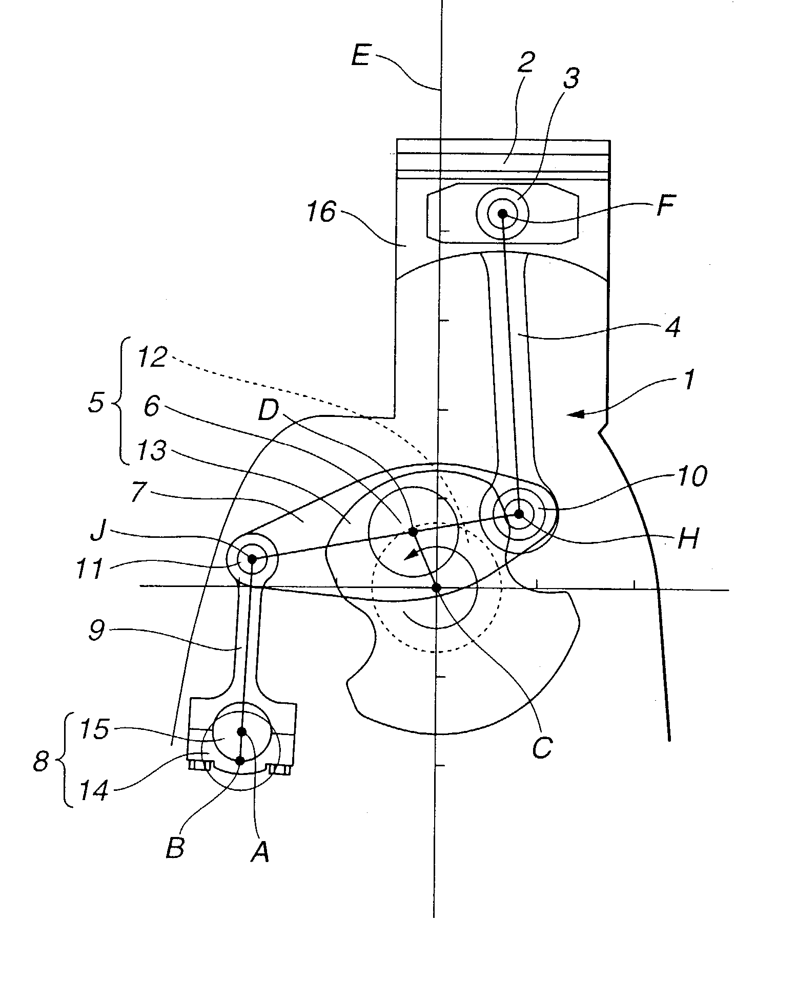
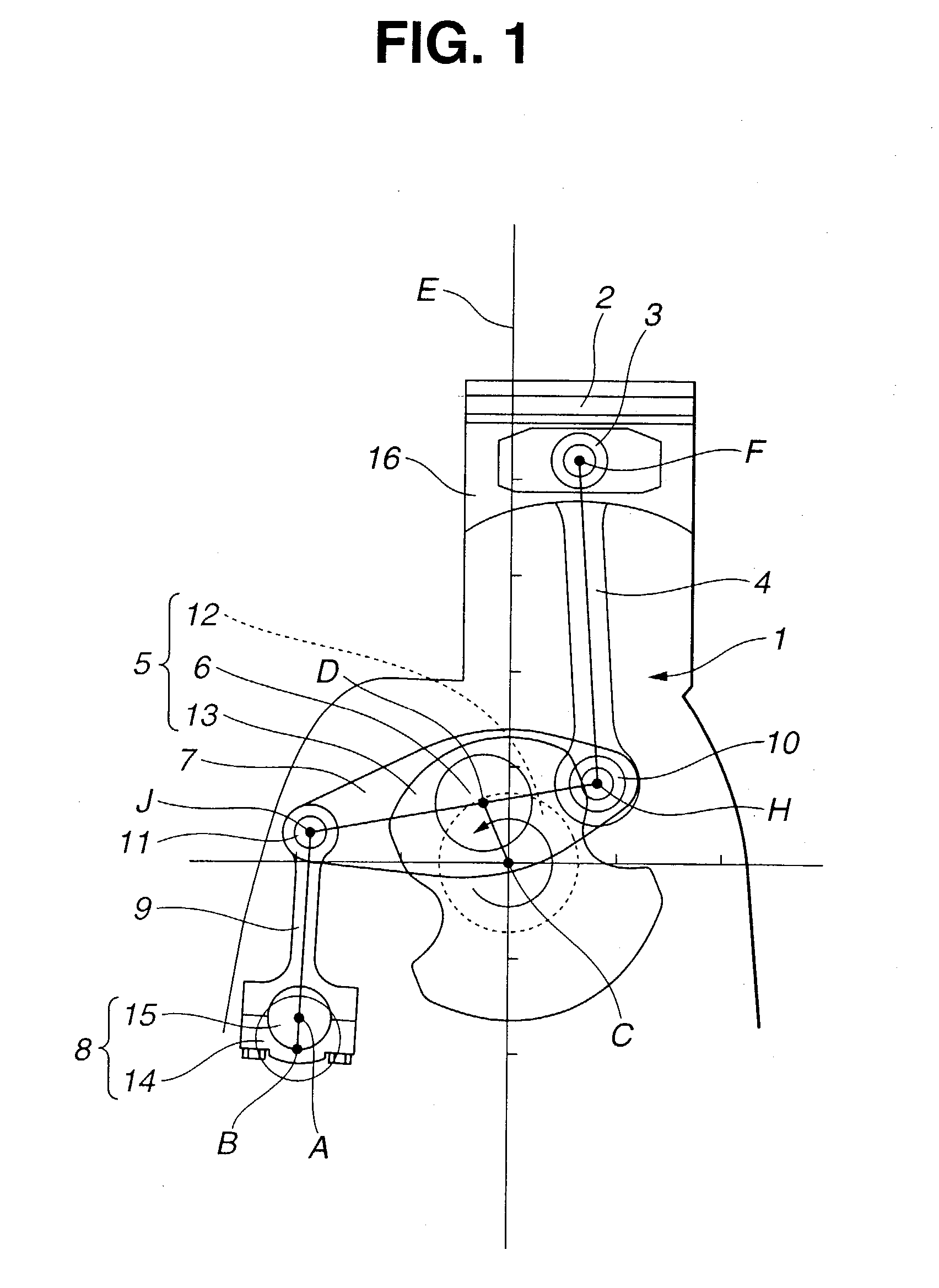
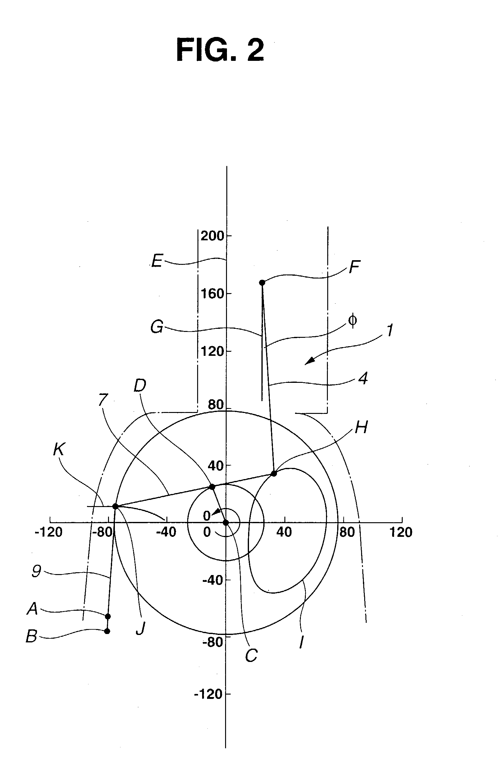
[0064] As is seen in FIG. 1 and FIG. 2, there is provided a link mechanism 1 of a reciprocating internal combustion engine, according to the present invention.

[0065] Link mechanism 1 includes an upper link 4, a lower link 7, a control shaft 8 and a control link 9.

[0066] Upper link 4 has a first end (upper in FIG. 1) connected to a piston pin 3 of a piston 2. Lower link 7 is connected to upper link 4, and to a crank pin 6 of a crank shaft 5. Control shaft 8 extends substantially in parallel with crank shaft 5. Control link 9 has a first end (lower in FIG. 1) swingably connected to control shaft 8, and a second end (upper in FIG. 1) connected to lower link 7. Control link 9 has a swingable center A which is offset from a rotational center B of control shaft 8. With respect to control shaft 8, control link 9 swings around swingable center A.

[0067] Upper link 4 and lower link 7 are connected to each other via an upper pin 10 in such a manner as to rotate relative to each other. Lower li...


PUM


Abstract

A link mechanism of an engine includes: an upper link having a first end connected to a piston pin of a piston; a lower link connected to the upper link via an upper pin having a center, the lower link being connected to a crank pin of a crank shaft; a control shaft extending substantially in parallel with the crank shaft, the control shaft having a rotational center; and a control link including: a first end swingably connected to the control shaft, and a second end connected to the lower link. In a process of the center of the upper pin moving nearer to the axial line of the piston pin, the center of the control pin moves in the upward direction, thus inclining the lower link and allowing the center of the upper pin and the center of the piston pin to move in the downward direction.

Description

[0001] 1. Field of the Invention[0002] The present invention relates to a link mechanism of a reciprocating internal combustion engine.[0003] 2. Description of the Related Art[0004] A conventional link mechanism of an internal combustion engine has a piston making a reciprocating motion which is transmitted to a crank shaft via a plurality of link members, thus rotating the crank shaft.[0005] As is seen in FIG. 8 and FIG. 9, Japanese Patent Unexamined Publication No. Heisei 9 (1997)-228858 (=JP9228858) discloses the link mechanism of the internal combustion engine.[0006] A lower link 42 is rotatably supported to a crank pin 41 of a crank shaft 40. Lower link 42 has a first end (left in FIG. 8) connected to a lower end of an upper link 44 via an upper pin 43. Lower link 42 has a second end (right in FIG. 8) connected to a lower end of a control link 46 via a control pin 45.[0007] Upper link 44 has an upper end connected to a piston 48 via a piston pin 47. Control link 46 has an upper...

Claims


Application Information

Patent Timeline
Patent Type & Authority Applications(United States)
IPC IPC(8): F02B75/04F02B75/32F02D15/02F16H21/20F16H21/34
CPCF02B75/048F02B75/045
Inventor MOTEKI, KATSUYAAOYAMA, SHUNICHIUSHIJIMA, KENSHIHIYOSHI, RYOSUKE
Owner NISSAN MOTOR CO LTD
Why Eureka
Try Eureka