Device and method for balancing rotating systems

a rotating system and rotating system technology, applied in the direction of mechanical control devices, process and machine control, instruments, etc., can solve the problems of irritating noise, shortening the service life of the particular rotating system, and component continuously rebalancing

Inactive Publication Date: 2004-01-08
ROBERT BOSCH GMBH
View PDF6 Cites 14 Cited by
  • Summary
  • Abstract
  • Description
  • Claims
  • Application Information

AI Technical Summary

Problems solved by technology

These unwanted vibrations can, among other effects, lead to irritating noises or--because of the greater load on the bearings--to a shortening of the service life of the particular rotating system.
Moreover, the applicable component is continuously rebalanced in operation, so that even imbalances that change over the course of operation or that even arise only during operation (for instance from wear, defects, dirt, or corrosion) are always automatically compensated for.
A disadvantage of the method, described in U.S. Pat. No. 5,724,862, for dynamic balancing of rotating bodies is, among others, that the balancing apparatus that carries the travel paths of the balancing bodies is relatively large, relatively complex in its construction, and thus also relatively heavy.

Method used


Image

  • Device and method for balancing rotating systems
  • Device and method for balancing rotating systems
  • Device and method for balancing rotating systems

Examples


third embodiment

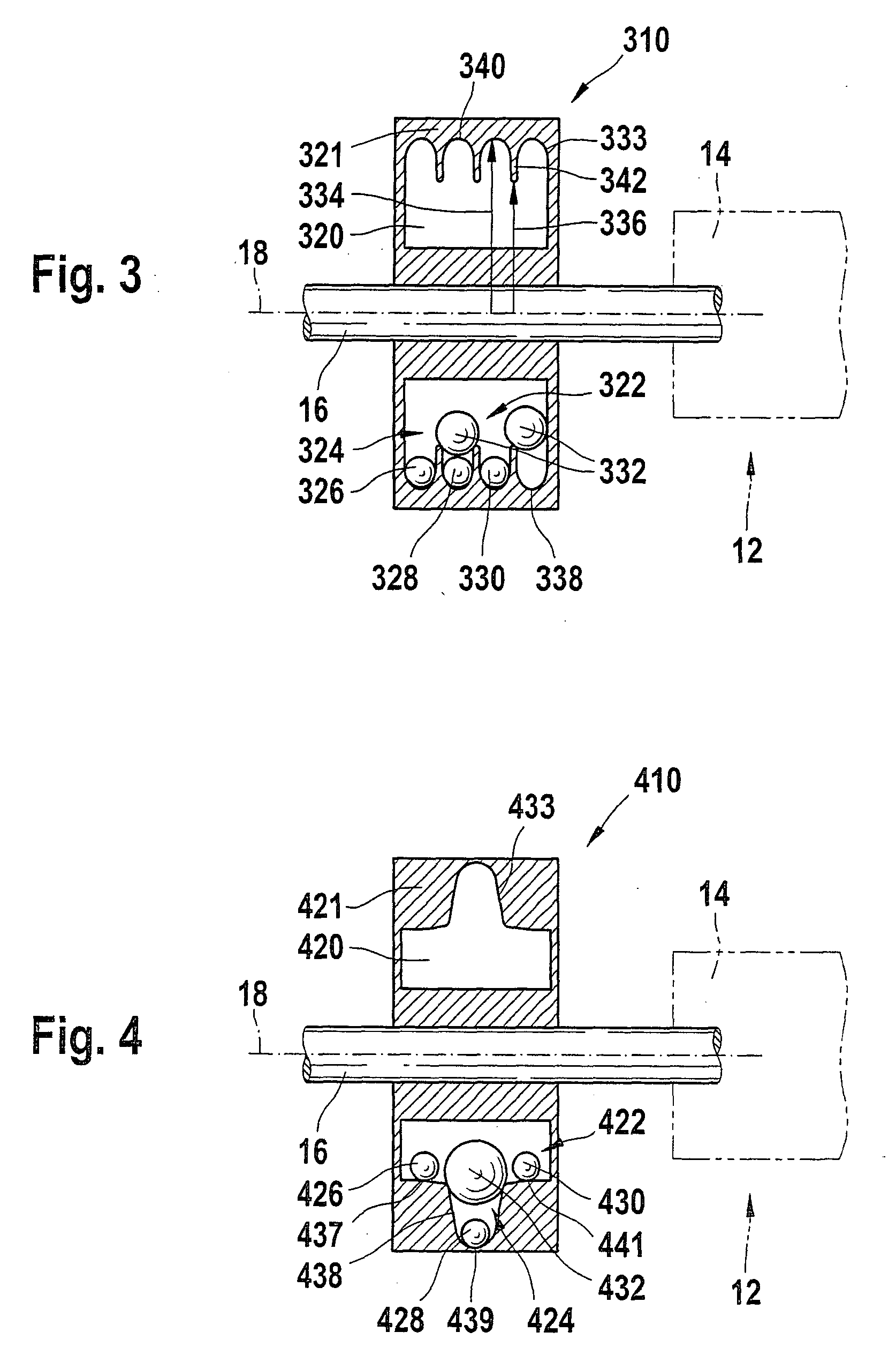
[0047] FIG. 3, in the apparatus 310 of the invention, shows a revolution conduit 320 that makes it possible for the balancing bodies 322, by reason of their different size, to be disposed along orbit paths of different radii 334 and 336. By means of a purposeful design of the geometry of the inner wall 338 of the outer side 340, that is, the side remote from the shaft 16, of the revolution conduit 320, the balancing bodies 322 can be selected and forced along the desired paths by means of the radii of curvature of the possible travel path cross sections. The mutual hindrance of the balls 324 is reduced markedly by the defined separation of the travel paths within the revolution conduit 320. The balls 324 are sorted by their diameters and travel along different travel paths about the shaft 16 of the system 12. This makes it possible for the required ball sizes, number of balls, and ball masses to be defined precisely for the sake of optimally reducing the imbalance of a rotating syst...

exemplary embodiment 6

[0056] In an augmentation of the exemplary embodiment of FIG. 5, the individual travel paths of the balancing apparatus 610 of the invention shown in FIG. 6 have, in addition to the radial staggering, an axial offset from one another in the direction of the pivot axis 18 of the rotating system 12. The axial offset of the travel paths in this exemplary embodiment is dependent on the ratio of the ball diameter to the travel path diameter. In exemplary embodiment 6, the largest balancing body 638 has the smallest spacing from the pivot axis 18 of the system 12. A free space 652 remains in the revolution conduit 620 axially next to the balancing body 638, and this space makes it possible for the balls 630 and 632 to find enough place axially next to the ball 638 even in the sectional plane of the apparatus 610 of the invention shown in FIG. 6. The balls 638 run in a kind of travel depression 654, which demarcates the travel path of the balls 638 from the further travel paths by means of...


PUM


Abstract

The invention relates to an apparatus and a method using the apparatus for automatically balancing rotating systems (12), having at least one travel path, disposed about the pivot axis (18) of the system (12), for at least one movable balancing body (522). It is proposed that the apparatus (510) have a closed revolution conduit (520), extending concentrically about the pivot axis (18), in which conduit the at least one balancing body (522) can orbit around the pivot axis (18) of the system over at least one of the existing travel paths open toward one another.

Description

PRIOR ART[0001] The present invention relates to a method and an apparatus for dynamically balancing rotating systems.[0002] Rotating systems are balanced in order to eliminate or reduce vibrations that occur in the system from imbalance. These unwanted vibrations can, among other effects, lead to irritating noises or--because of the greater load on the bearings--to a shortening of the service life of the particular rotating system.[0003] In addition to static balancing, in which a defined exemplary embodiment mass is fixedly mounted on or removed from a previously determined point of the rotating system, so-called automatic balancing has also long been known. In this method, balancing bodies are used that are movable about the pivot axis of the rotating system.[0004] In automatic balancing, the balancing bodies that are movable about the pivot axis of the rotating system order themselves automatically in such a way that the forces of inertia from the original imbalance are reduced,...

Claims


Application Information

Patent Timeline
Patent Type & Authority Applications(United States)
IPC IPC(8): F16F15/14F16F15/36
CPCY10T74/2111F16F15/363F16F15/22
Inventor NEUBAUER, ACHIMBOLZ, MARTIN-PETERMOENCH, JOCHENKRUEGER, HARTMUT
Owner ROBERT BOSCH GMBH
Why Eureka
Try Eureka