Eureka AIR delivers breakthrough ideas for toughest innovation challenges, trusted by R&D personnel around the world.

Inverted aerosol dispenser

a dispenser and aerosol technology, applied in the direction of liquid dispensing, packaging, transportation and packaging, etc., can solve the problems of loss of aerosol propellant and depletion of aerosol propellan

Inactive Publication Date: 2004-01-22
SEAQUIST PERFECT DISPENSING FOREIGN INC
View PDF33 Cites 9 Cited by
  • Summary
  • Abstract
  • Description
  • Claims
  • Application Information

AI Technical Summary

Benefits of technology

[0028] Another object of the present invention is to provide an inverted aerosol dispensing device that incorporates a wide base of undercap to provide a more stable base for storage relative to a conventional overcap mounted to a top portion of the aerosol container.
[0032] Another object of the present invention is to provide an inverted aerosol dispensing device which is easier to dispense an aerosol product into the hand of a user relative to a conventional aerosol dispensing device.
[0036] Another object of the present invention is to provide an inverted aerosol dispensing device which is economical to manufacture and is economical to install on the aerosol dispensing device.

Problems solved by technology

The high viscosity foaming aerosol products that are dispensed in an inverted position are not designed to dispense in an upright position.
This loss of the aerosol propellant may deplete the aerosol propellant prior to the complete dispensing of the aerosol product from the aerosol container.

Method used


Image

  • Inverted aerosol dispenser
  • Inverted aerosol dispenser
  • Inverted aerosol dispenser

Examples


first embodiment

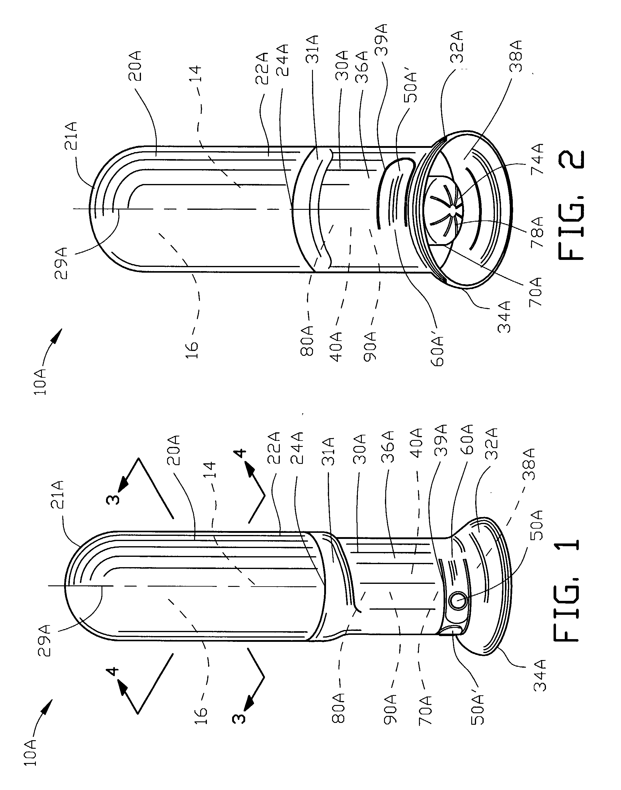
[0152] FIGS. 1 and 2 are top and bottom isometric views of an aerosol dispensing device 10A for dispensing an aerosol product 14 incorporating the present invention. The aerosol dispensing device 10A dispenses the aerosol product 14 through an aerosol propellant 16 from an aerosol container 20A.

[0153] The aerosol dispensing device 10A of the present invention enables the aerosol container 20A to be stored in an inverted position. The aerosol dispensing device 10A dispenses the aerosol product 14 under the pressure of the aerosol propellant 16 in a generally downward direction through the undercap 30A. The invention is particularly useful in dispensing viscous aerosol products 14.

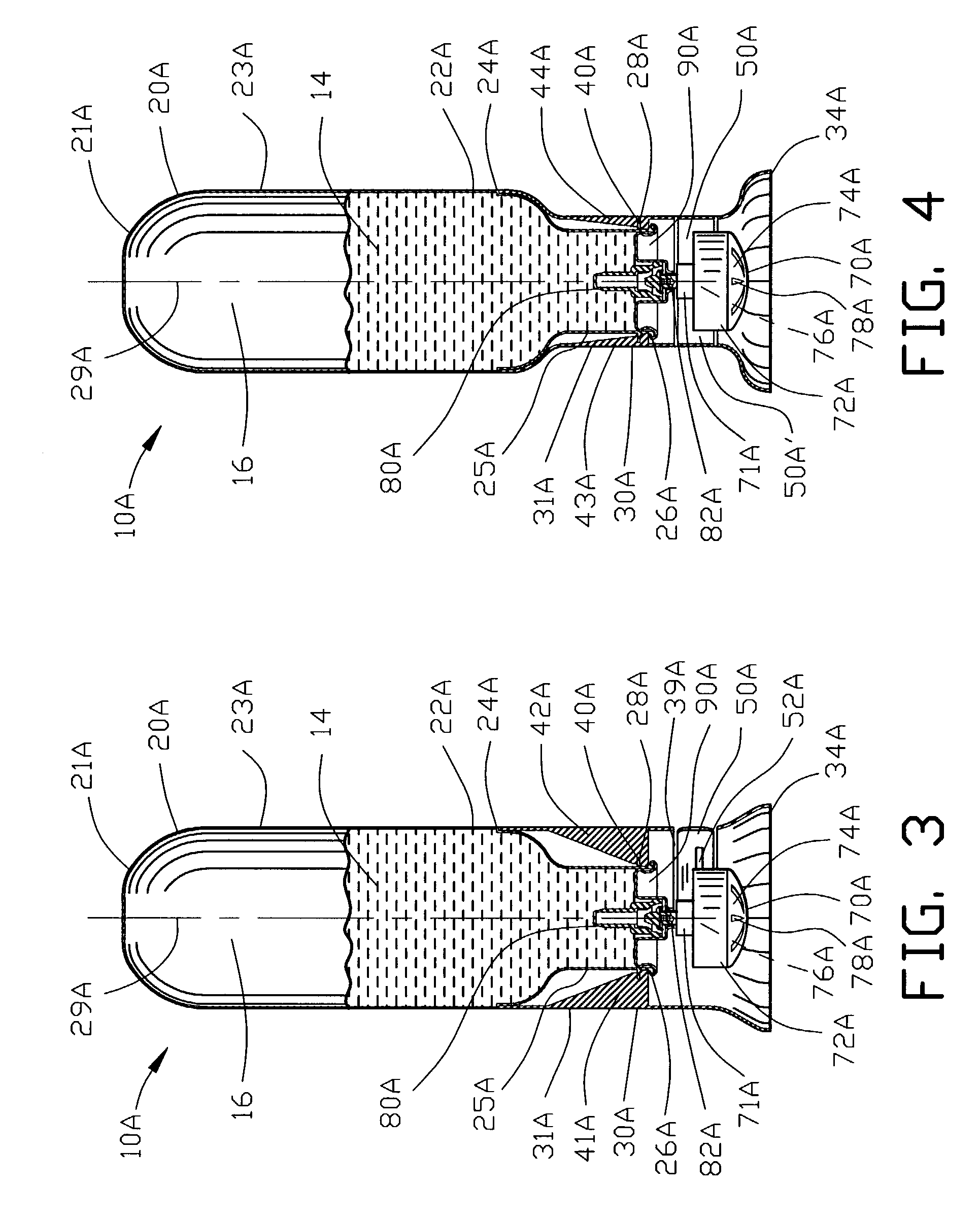
[0154] FIGS. 3 and 4 are sectional views of FIG. 1 illustrating an undercap 30A secured to the aerosol container 20A by a mounting 40A for supporting the aerosol container 20A. The undercap 30A includes an actuator 50A pivotably connected to the undercap 30A by a hinge 60A. The actuator 50A is positioned for...

fifth embodiment

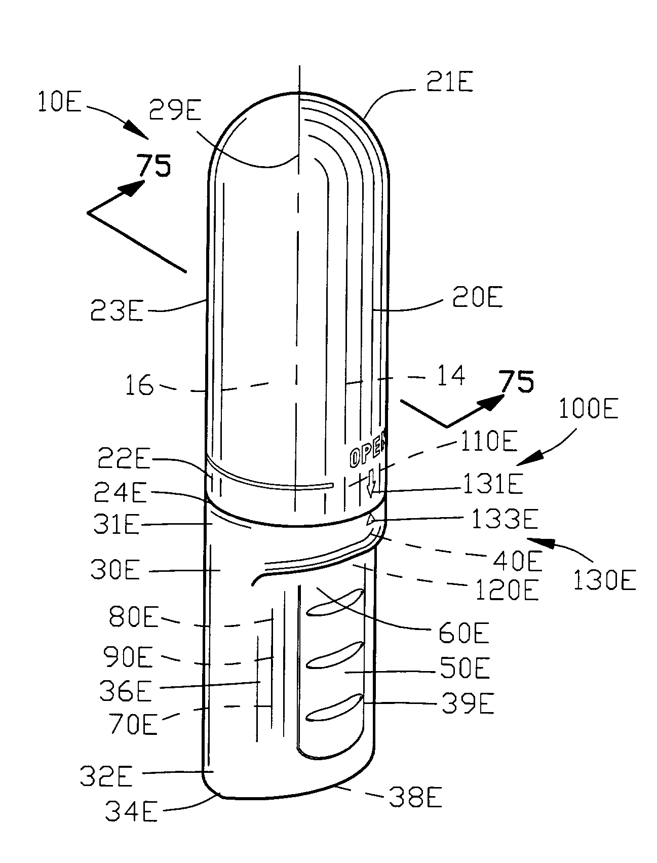
[0211] the aerosol dispensing device 10E includes a locator 100E for locating the undercap 30E in the first and second first rotational positions relative to the aerosol container 20E. In this embodiment of the invention, the locator 100E comprises a container locator 110E defined by the aerosol container 20E and an undercap locator 120E defined by the undercap 30E. The container locator 110E cooperates with the undercap locator 120E for locating the undercap 30E in the first rotational position relative to the aerosol container 20E.

[0212] The aerosol dispensing device 10E may optionally include an indicator 130E for indicating the position of the undercap 30E relative to the aerosol container 20E. The indicator 130E comprises container indicators 131E and 132E cooperating with an undercap indicator 133E for indicating the first and second first rotational positions of the undercap 30E relative to the aerosol container 20E.

[0213] FIGS. 73 and 75 illustrate the undercap 30E rotated i...


PUM


Abstract

An inverted aerosol dispensing device is disclosed having an undercap rotatably secured to the aerosol container with a bottom portion of the undercap supporting the aerosol container on a supporting surface to store the aerosol dispensing device in an inverted position. The undercap is rotatable into a first rotational position for enabling an actuator to discharge an aerosol product in a generally downwardly direction. The undercap is rotatable into a second rotational position for inhibiting the actuator from moving the valve stem.

Description

[0001] 1. Field of the Invention[0002] This invention relates to aerosol dispensing devices and more particularly to an improved aerosol dispensing device for discharging an aerosol product in a generally downwardly direction.[0003] 2. Description of the Prior Art[0004] An aerosol dispensing device comprises an aerosol valve located internal an aerosol container. The aerosol valve is biased into a closed position. A valve stem cooperates with the aerosol valve for opening the aerosol valve. An actuator engages with the valve stem to open the aerosol valve for dispensing an aerosol product from the aerosol container. The aerosol product is dispensed from the aerosol valve through a spray nozzle.[0005] Various types of actuators have been utilized by the prior art for actuating an aerosol dispensing device. The first and the most basic type of actuator for an aerosol dispensing device is an actuator button that is affixed to the valve stem. A depression of the actuator button depresse...

Claims


Application Information

Patent Timeline
IPC IPC(8): B65D83/14B65D83/16
CPCB65D83/206B65D83/22B65D83/75
Inventor WALTERS, PETER J.YERBY, PATRICK TIMOTHYBRAUN, CRAIG A.
Owner SEAQUIST PERFECT DISPENSING FOREIGN INC
Why Eureka
Eureka Blog
Learn More