Snap-in washers and assemblies thereof

a technology of washers and washers, applied in the field of spinal fixation connecting devices, can solve the problems of large number of separate parts and cumbersome use of washers

Inactive Publication Date: 2004-05-06
DEPUY ACROMED INC
View PDF63 Cites 204 Cited by
  • Summary
  • Abstract
  • Description
  • Claims
  • Application Information

AI Technical Summary

Problems solved by technology

Disadvantages of this system are the large number of separate parts and that the wa

Method used


Image

  • Snap-in washers and assemblies thereof
  • Snap-in washers and assemblies thereof
  • Snap-in washers and assemblies thereof

Examples


Embodiment Construction

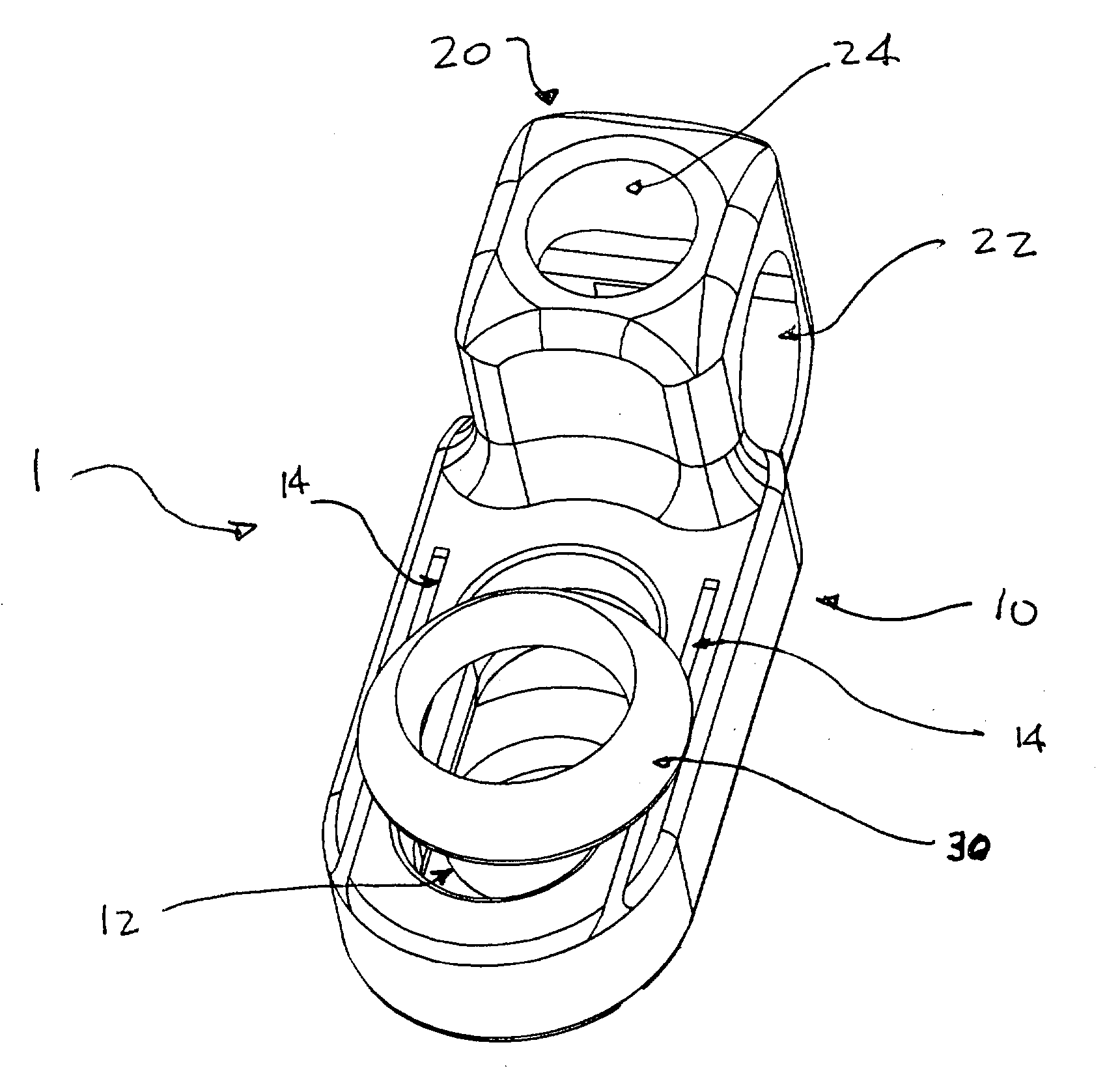
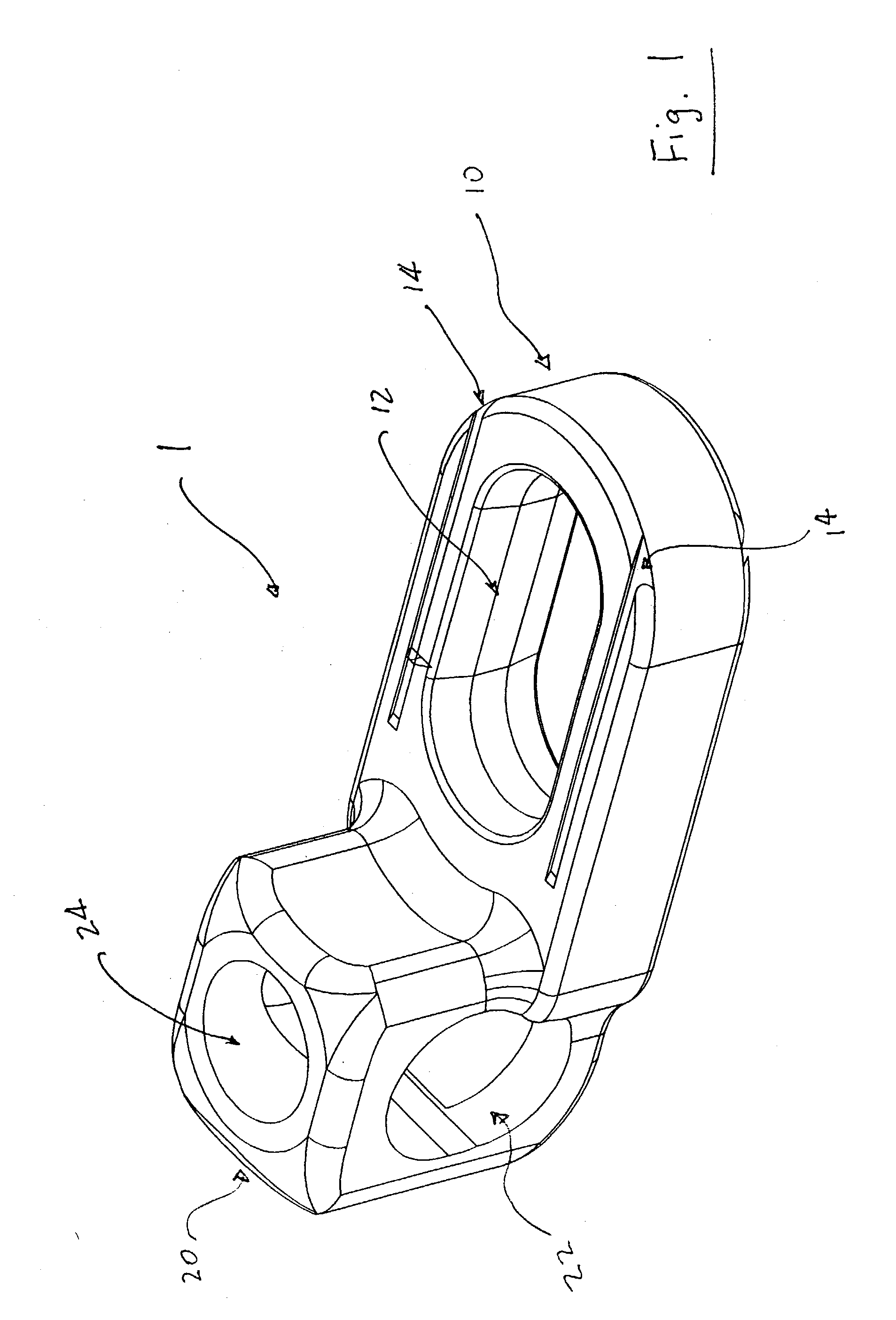
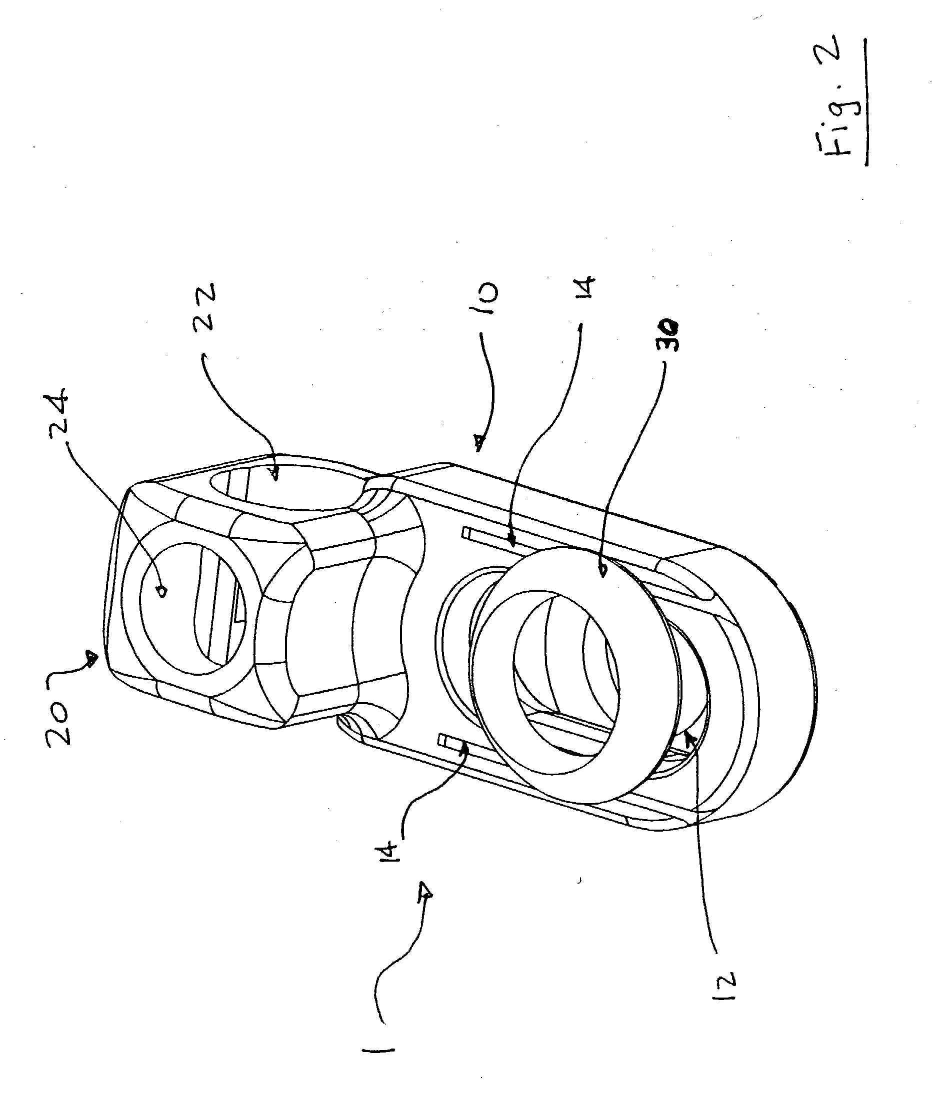
[0029] Generally, this invention deals with devices for spinal fixation especially to those used particularly for joining a bone anchor with spinal stabilizers such as a spinal rod or spinal plate in a polyaxial fashion. The invention is also directed to polyaxial connectors which incorporate arcuate washers. The polyaxial features of this invention are achieved preferably with snap-in washers which minimize the numbers of parts that a surgeon may have to handle during surgery.

[0030] FIG. 1 depicts spinal stabilizer-bone anchor connector 1. Connector 1 comprises spinal stabilizer portion 20 and bone anchor portion 10. Spinal stabilizer portion 20 comprises a stabilizer receiving throughbore 22 and a set screw bore 24. Thus in attaching to a stabilizer, a stabilizer (rod) will pass through bore 22 and be secured into place by the locking of a set screw through bore 22 by securely contacting the stabilizer. Portion 10 of the device includes aperture 12 for receiving a head of a bone a...


PUM


Abstract

This invention relates to an apparatus for spinal fixation, in particular, for joining a bone anchor with spinal stabilizers such as a spinal rod or spinal plate in a polyaxial fashion. The invention is also directed to polyaxial connectors which incorporate arcuate washers. The polyaxial features of this invention are achieved preferably with snap-in washers which minimize the numbers of parts that a surgeon may have to handle during surgery.

Description

[0001] 1. Field of the Invention[0002] This invention relates to connecting devices for spinal fixation, in particular, for joining a bone anchor with spinal stabilizers such as a spinal rod or spinal plate in a polyaxial fashion.[0003] 2. Related Art[0004] It is well know and practiced that when securing and maintaining bones in a preferred alignment, a plurality of bone anchors may be attached to one or more bones and subsequently secured together in a desired orientation with a bone stabilizer. Examples of bone stabilizers include "longitudinal members," and in some cases, "connectors" as is known in the art. That is, the longitudinal member (e.g. a rod or a plate) connects the bone anchors together, and (if needed), the connectors are used to secure the bone anchor to the longitudinal member. Accordingly, there are at least two criteria that would be desirable to be satisfied when securing bones in a desired alignment using bone anchors and a bone stabilizer:[0005] (i) it is des...

Claims


Application Information

Patent Timeline
IPC IPC(8): A61B17/58A61B17/70A61B17/86
CPCA61B17/7035A61B17/8695A61B17/7044A61B17/7041
Inventor BONO, FRANK S.BORGSTROM, AMIEDUNBAR, WILLIAM JR.FAIR, CHRIS
Owner DEPUY ACROMED INC
Why Eureka
Try Eureka