Light guiding plate and liquid crystal display device with the light guiding plate

Inactive Publication Date: 2004-07-22
FUJI ELECTRIC CO LTD
View PDF0 Cites 53 Cited by
  • Summary
  • Abstract
  • Description
  • Claims
  • Application Information

AI Technical Summary

Benefits of technology

[0234] Next, this structure is described. Since a light guiding plate 1 improves the luminance improvement ratio of polarized light in one direction, how the light guiding plate 1 influences light inputted from a light source 2 is described below.
[0515] As a result, polarized components orthogonal to the grating structure (polarized components p) can transmit through this grating structure and can light a target to be lit, and accordingly, light inputted to a light guiding means from a light source can be efficiently used.

Problems solved by technology

However, the liquid crystal panel itself is a device to be lit using polarized light having a prescribed direction, and half of the quantity of light inputted to the liquid crystal panel is eliminated by a polarization plate and is not used, which is a problem.
The addition of the new parts incurs the large size and high cost of the entire device, which is a problem.

Method used


Image

  • Light guiding plate and liquid crystal display device with the light guiding plate
  • Light guiding plate and liquid crystal display device with the light guiding plate
  • Light guiding plate and liquid crystal display device with the light guiding plate

Examples


Embodiment Construction

)

[0517] FIGS. 57 through 60 show the rough structures of other preferred embodiments of the present invention. These are sequentially described below. However, the present invention is also applicable to a variety of liquid crystal display devices, etc., other than those shown in FIGS. 57 through 60.

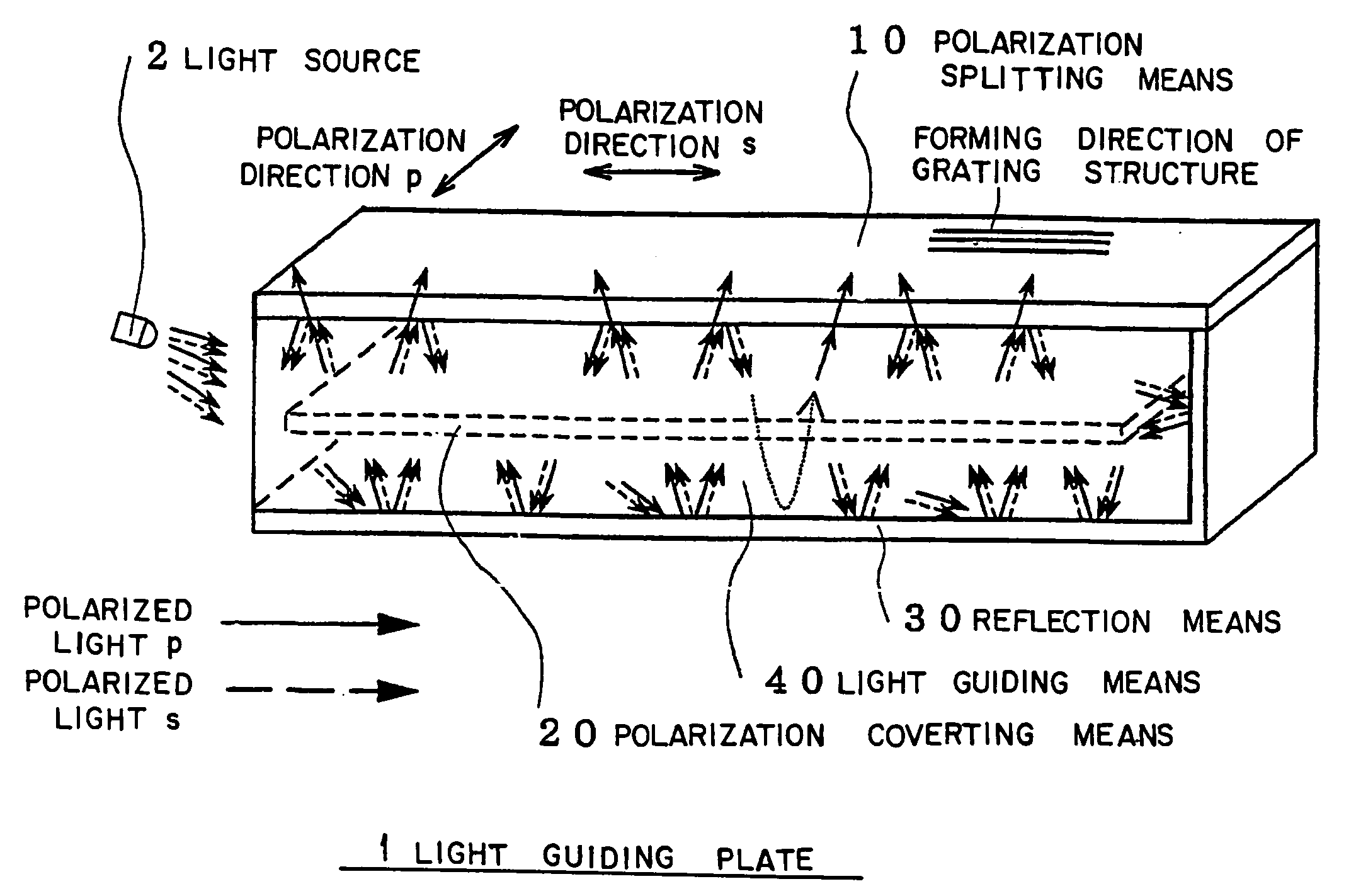
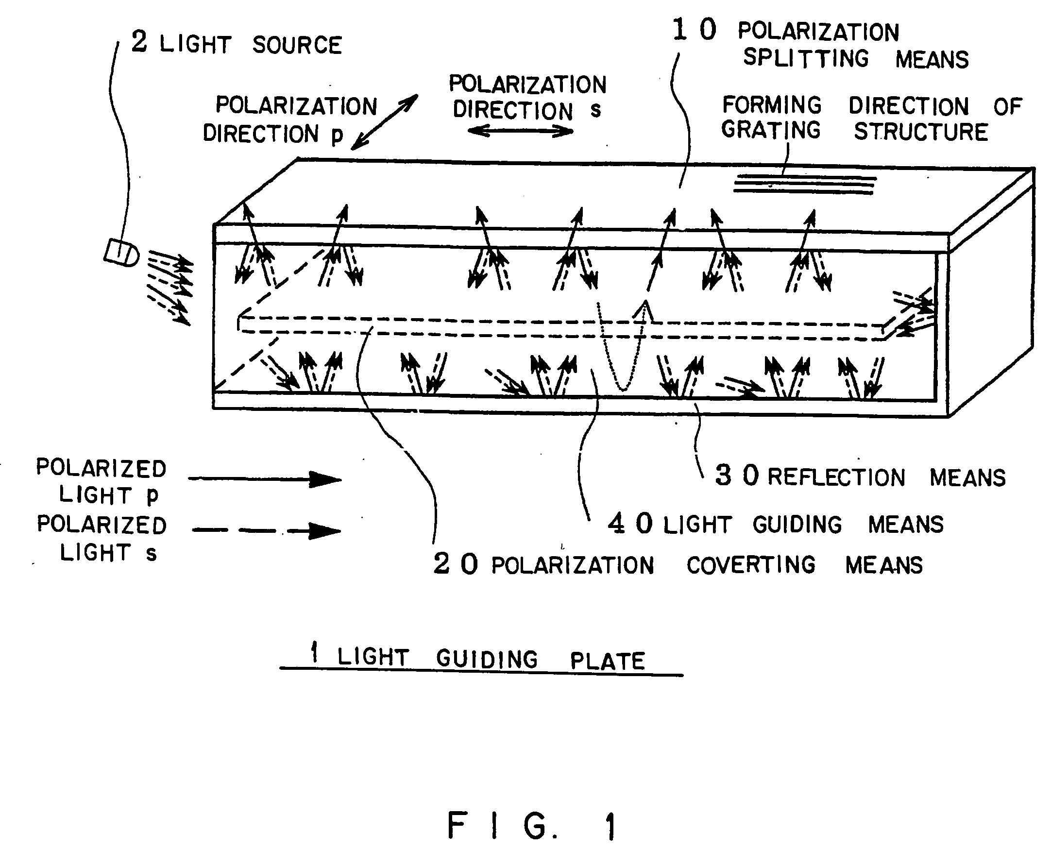
[0518] Firstly, FIG. 57 shows the case where the present invention is applied to a directly-under lighting type liquid crystal display. Light emitted from the light source 2, such as a fluorescent tube, etc., passes through a light guiding means 450 (concept including all the light guiding plates 1 in the preferred embodiments described above; this is also used in the following preferred embodiments) and reaches a grating portion (concept including all the grating structures in the preferred embodiments described above; this is also used in the following preferred embodiments).

[0519] Polarized light is divided into two polarized components on a grating surface, and one polarized componen...


PUM


Abstract

A light guiding plate capable of extracting the polarized component of light that was not utilized effectively, reducing the number of parts such as light emitting elements, and reducing a power consumption and a liquid crystal display device having the light guiding plate; the light guiding plate (1), comprising a light guiding means (40) for guiding the light incident from a light source (2), a polarizing and splitting means (10) allowing the outgoing of only the polarization in one direction, a reflection means (30) for reflecting the light, and a light converting means (20) disposed between the polarizing and splitting means (10) and the reflection means (30) and converting the polarization direction of the light transmitted therethrough.

Description

[0001] The present invention relates to a light guiding plate emitting polarized light in a predetermined direction such as the light for lighting of a liquid crystal panel and a liquid crystal display device using this guiding plate.[0002] In a liquid crystal display device using a liquid crystal panel 5' used in the display device of a data terminal, etc., the liquid crystal panel 5'. is used, for example, together with the lighting device 6' shown in FIG. 65 since it itself does not emit light. The lighting device 6' shown in FIG. 65 comprises a light source 2', such as a cold cathode tube, a light guiding means 40' made of a transparent material and a reflection means 30' (30a' and 30b').[0003] Light 3a' emitted from the light source 2' enters the light guiding means 40', advances through the light guiding means while being repeatedly reflected on the reflection means 30' and is emitted in the direction of the liquid crystal panel 5'. In this case, in order to uniformly light th...

Claims


Application Information

Patent Timeline
IPC IPC(8): F21V8/00G02B6/00
CPCG02B6/0001G02B6/0038G02B6/0046G02B6/0068G02B6/0056G02B6/0065G02B6/005G02F1/1335
Inventor TANAKA, HIDEYUKIKANNO, TOSHIYUKIKOBAYASHI, TAKESHIFURUKAWA, MASAHARUSAITO, TETSUYAYOKOMORI, NORIHARUSUZUKI, YOSHIYUKI
Owner FUJI ELECTRIC CO LTD
Why Eureka
Try Eureka