Optical head for receiving light and optical system using the same

Active Publication Date: 2017-10-26
OTO PHOTONICS
View PDF2 Cites 0 Cited by
  • Summary
  • Abstract
  • Description
  • Claims
  • Application Information

AI Technical Summary

Benefits of technology

[0012]In the optical head described above, the scattered light from the cosine corrector may be reflected by the reflector or the reflective section. The scattered light not yet entering the optical output section may be recycled by the reflector and may enter the optical output section, thus enhancing the ratio of the scattered light entering the optical output section. As a result, the amount of incident light collected by the optical head may be increased. In addition, using the cosine corre

Problems solved by technology

Conventional optical systems that are commonly used in a laboratory setting tend to be easily damaged and need frequent calibration.
However, although substantially the same transmittance for light

Method used


Image

  • Optical head for receiving light and optical system using the same
  • Optical head for receiving light and optical system using the same
  • Optical head for receiving light and optical system using the same

Examples


Example

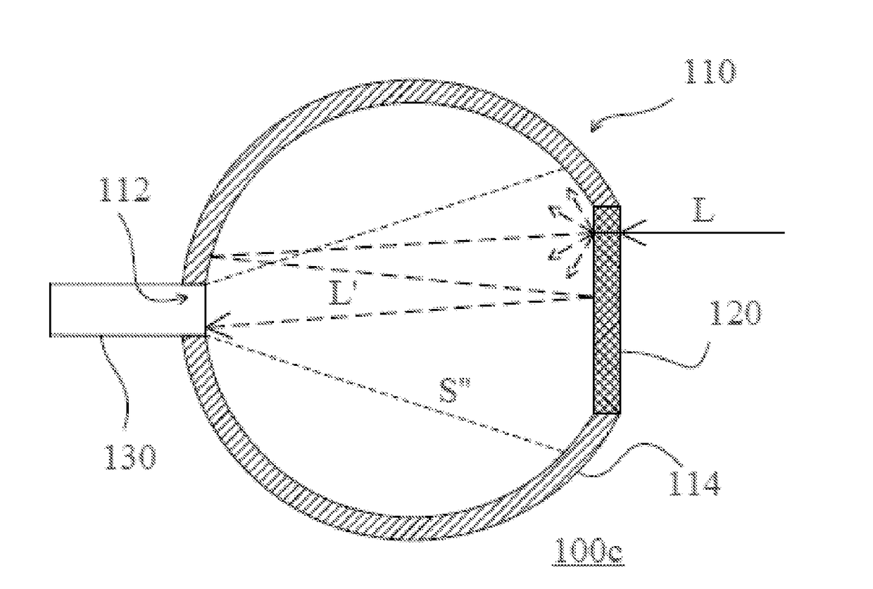
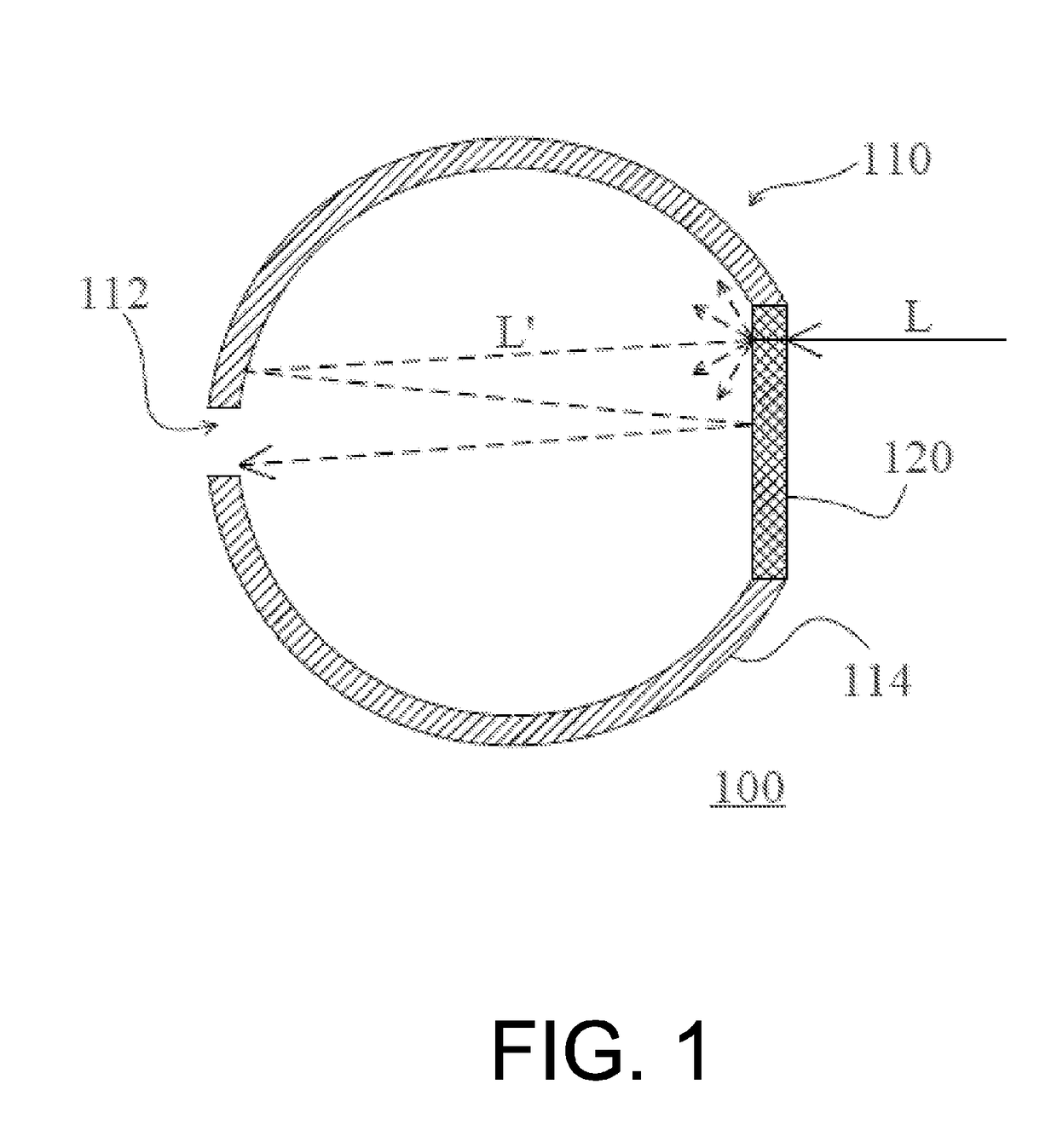
[0023]FIG. 1 is a side view of an optical head in accordance with one embodiment of the present invention. Referring to FIG. 1, the optical head 100 for receiving incident light L includes a reflector 110 and a transmissive cosine corrector 120 facing the reflector 110. The reflector 110 includes an optical output section 112 for transmitting light and a reflective section 114. Thus, scattered light L′ in a Lambertian pattern, which is converted from the incident light L after the incident light L is incident on the transmissive cosine corrector 120, may be measured. When light is incident on the transmissive cosine corrector 120, the scattered light in a Lambertian pattern will be generated on both sides of the transmissive cosine corrector 120. The intensity of the scattered light will not be affected by incident angles of the incident light. More specifically, light rays incident on the transmissive cosine corrector 120 at different angles have substantially the same transmittanc...


PUM


Abstract

An optical head for receiving an incident light is provided. The optical head comprises a reflective diffuser and a reflector disposed to face the reflective diffuser. The reflective diffuser is disposed in an optical path of the incident light and shields the reflector from the incident light. The reflective diffuser converts the incident light to scattered light having a Lambertian pattern. The reflector has an optical output section that transmits the scattered light and a reflective section that reflects the scattered light to the reflective diffuser and/or the other portions of the reflective sections. An optical system using the optical head is also provided.

Description

CROSS-REFERENCE TO RELATED PATENT APPLICATIONS[0001]This application is a divisional application of U.S. patent application Ser. No. 14 / 052,204 filed on Oct. 11, 2013, which claims benefit of Taiwanese patent application Ser. No. 101138142 filed on Oct. 16, 2012. The entirety of the above-mentioned patent applications are hereby incorporated by reference and made a part of this specification.FIELD OF THE INVENTION[0002]The present invention relates to an optical component, and more particularly to an optical head for receiving incident light.BACKGROUND OF THE INVENTION[0003]Optical systems, such as spectrometers and lux meters, have been widely used in numerous industries, including: biotechnology, environmental technology, electronics, food and beverage, industrial chemicals, materials, and pharmaceuticals. With the development of optoelectronics, the trend is to miniaturize the sizes of optical systems. Conventional optical systems that are commonly used in a laboratory setting te...

Claims


Application Information

Patent Timeline
IPC IPC(8): G02B5/02G01J1/02G01J3/02G01J1/42G01J1/04G01J3/18G02B19/00
CPCG02B5/0273G01J3/18G01J3/0297G01J3/0232G01J3/0218G01J3/0216G01J3/0205G01J3/021G01J1/42G01J1/0474G01J1/0425G01J1/0422G01J1/0414G01J1/044G01J1/0295G02B19/0076
Inventor HUNG, CHIEN-HSIANG
Owner OTO PHOTONICS
Why Eureka
Try Eureka