Biosensor

Inactive Publication Date: 2011-05-12
ALL MEDICUS CO LTD
View PDF4 Cites 1 Cited by
  • Summary
  • Abstract
  • Description
  • Claims
  • Application Information

AI Technical Summary

Benefits of technology

[0031]According to the biosensor of the present invention in which the sensing electrodes are formed on the upper insulating substrate and the lower insulating substrate such that, using the sensing electrodes, the measuring device can determine whether a sample (e.g., blood) is completely filled in the sample path when the sample is injected through the sample injection port, thus obtaining a more accurate measuremen

Problems solved by technology

Compared to the electrochemical method, the chromatographic method has difficulties in analyzing critical biomaterials because the measurement time is long, a large amount of same is required, and measurement errors occur due to turbidity in biological samples.
However, since the reaction takes place immediately after the blood is in contact with the second electrode 13, the m

Method used


Image

  • Biosensor
  • Biosensor
  • Biosensor

Examples


first embodiment

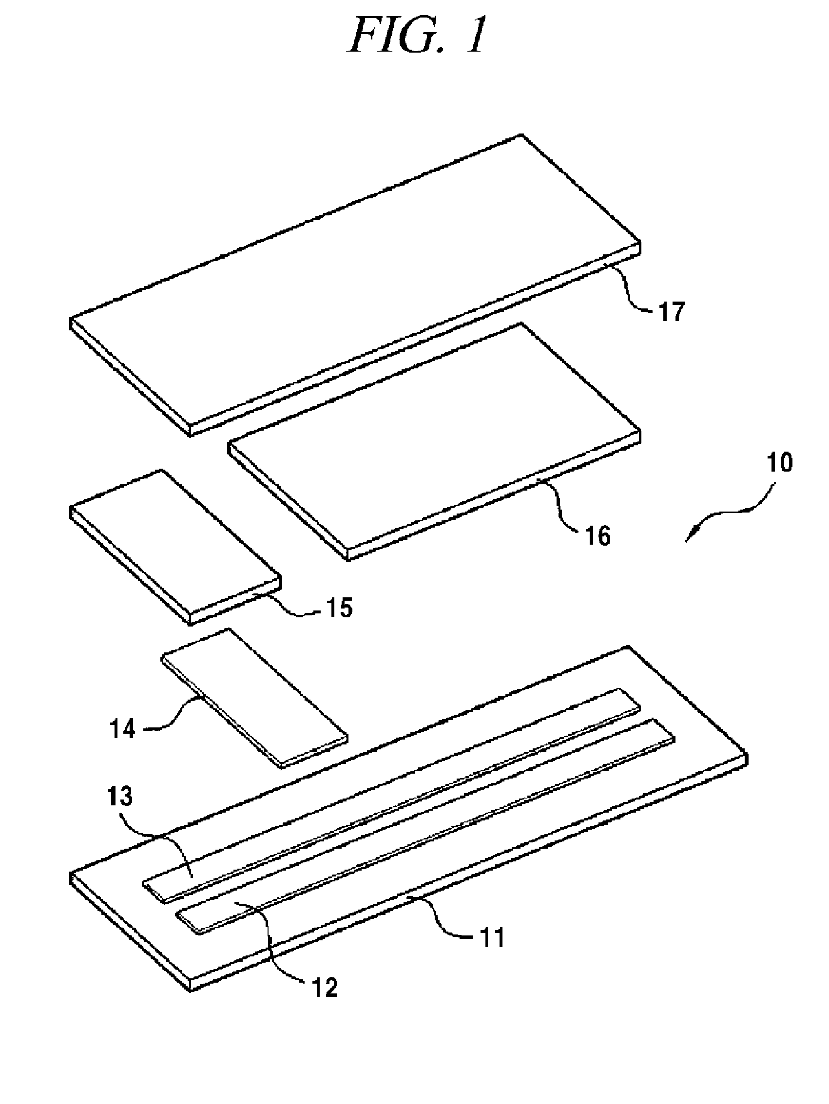
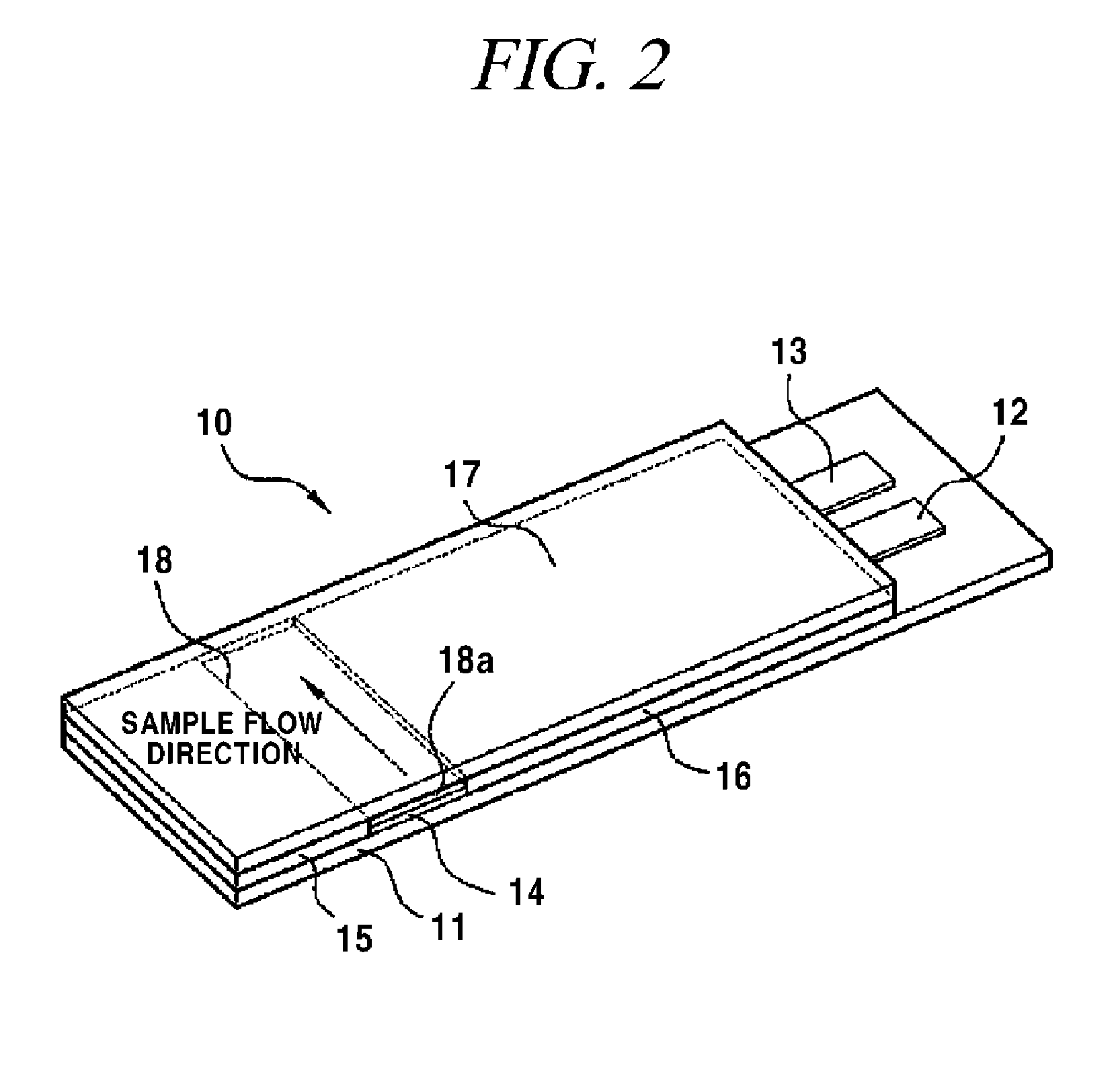
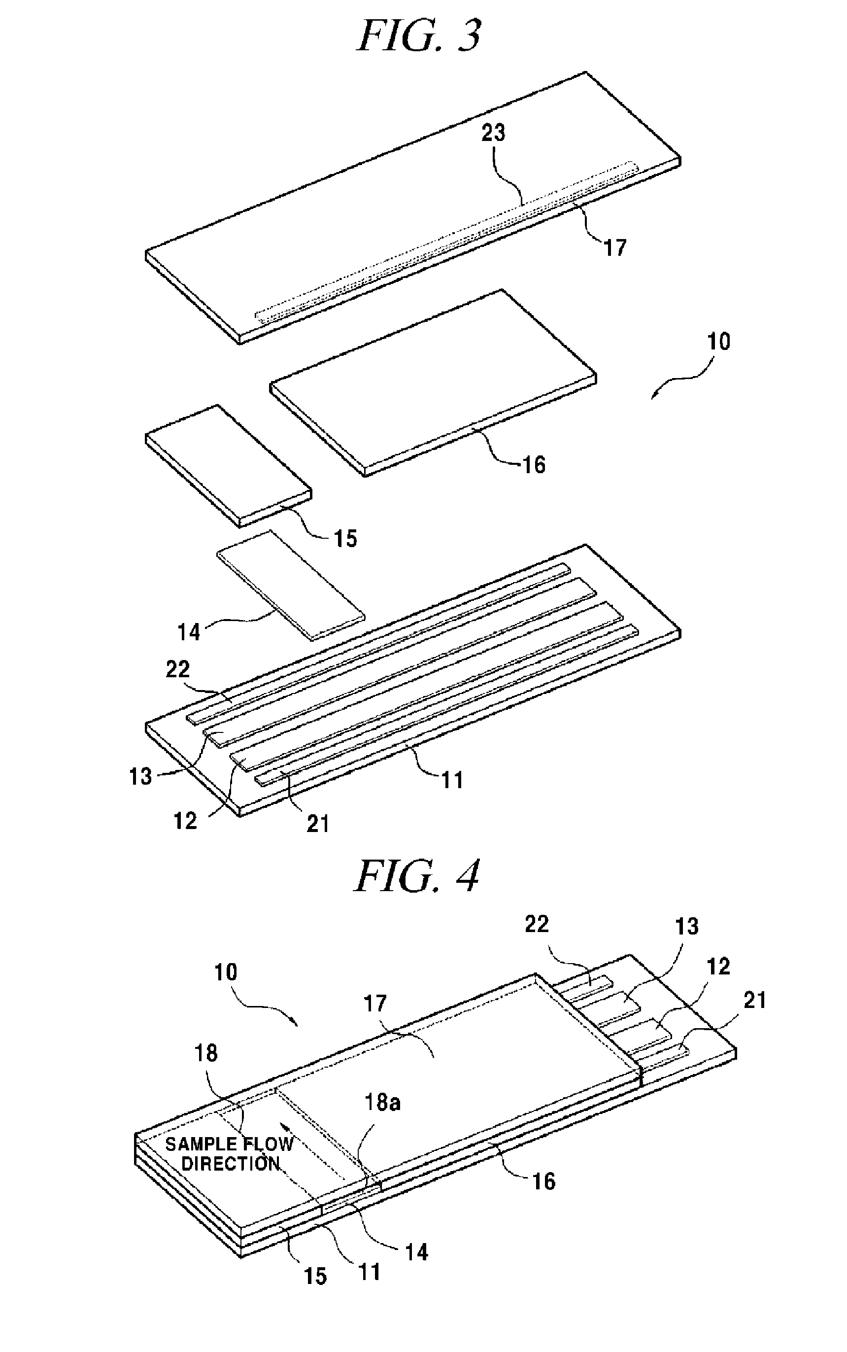
[0041]FIGS. 3 and 4 are perspective views showing a biosensor in accordance with the present invention, in which FIG. 3 is an exploded perspective view and FIG. 4 is an assembled perspective view.

[0042]As shown in FIGS. 3 and 4, a biosensor 10 includes an upper insulating substrate 17, a lower insulating substrate 11, a working electrode 12, a reference electrode 13, spacers 15 and 16, and an enzyme reaction layer 14. The working electrode 12 and the reference electrode 13 are formed on an upper surface (inner surface) of the lower insulating substrate 11. The spacers 15 and 16 are interposed between the upper insulating substrate 17 and the lower insulating substrate 11 to form a sample path 18. The enzyme reaction layer 14 is immobilized onto the working electrode 12 and the reference electrode 13 along the sample path 18 in the width direction.

[0043]In the first embodiment of the present invention, the biosensor 10 further includes sensing electrodes 21 and 23 formed on the inner...

second embodiment

[0052]In the above-described second embodiment, the first upper sensing electrode 23 and the first lower sensing electrode 21 are used to determine whether the sample is injected. When the sample is injected through the sample injection port 18a and comes in contact with the first upper sensing electrode 23 and the first lower sensing electrode formed around the sample injection port 18a, the time point at which the first upper sensing electrode 23 and the first lower sensing electrode 21 are electrically connected to each other by the sample is detected.

[0053]The second upper sensing electrode 24 and the second lower sensing electrode 22 are used to determine whether the sample is completely filled in the sample path 18 as it reaches the reference electrode 13. The time point at which the sample sequentially passes through the first lower sensing electrode 21, the working electrode 12, and the reference electrode 13 and reaches the second upper sensing electrode 24 and the second l...

third embodiment

[0058]Meanwhile, FIG. 6 is an exploded perspective view showing a biosensor in accordance with the present invention. In this embodiment, three electrodes are formed on the lower insulating substrate 11 by adding a lower sensing electrode 21 around the sample injection port 18a, i.e., at the outside of the working electrode 12, in addition to the working electrode 12 and the reference electrode 13. Moreover, an upper sensing electrode 24 is formed on the upper insulating substrate 17 at the opposite side of the sample injection port 18a (at a side far away from the sample injection port 18a). The upper sensing electrode 24 on the upper insulating substrate 17 is positioned at the outside of the reference electrode 13 at a predetermined distance when the upper and lower insulating substrates 11 and 17 are bonded.

[0059]In the above-described third embodiment, the lower sensing electrode 21 and the upper sensing electrode 24 are used to determine whether the sample is completely filled...


PUM


Abstract

Disclosed herein is a biosensor, in which sensing electrodes are formed on an upper insulating substrate and a lower insulating substrate such that, using the sensing electrodes, a measuring device can determine whether a sample (e.g., blood) injected through a sample injection port is completely filled in a sample path and determine a time point at which the sample is injected and a time point at which the sample is completely filled. Therefore, it is possible to estimate the flow characteristics of the sample and the flow rate and use the estimated values to correct the measurement result, thus obtaining a more accurate measurement result.

Description

TECHNICAL FIELD[0001]The present invention relates to a biosensor and, more particularly, to a biosensor, in which sensing electrodes are formed on an upper insulating substrate and a lower insulating substrate such that, using the sensing electrodes, a measuring device can determine whether a sample (e.g., blood) injected through a sample injection port is completely filled in a sample path and determine a time point at which the sample is injected and a time point at which the sample is completely filled. Therefore, it is possible to estimate the flow characteristics and the flow rate of the sample and use the estimated values to correct the measurement result, thus obtaining a more accurate measurement result.BACKGROUND ART[0002]A biosensor is a device that converts information on an analyte into a detectable signal such as a color, fluorescent, or electrical signal using a biological component or imitating the biological component.[0003]Especially, since a biosensor that utilize...

Claims


Application Information

Patent Timeline
IPC IPC(8): C12M1/34
CPCC12Q1/001G01N27/3272C12Q1/006G01N33/48G01N27/26G01N27/00
Inventor AHN, YON CHANCHOI, YONG BOKPARK, MI SUK
Owner ALL MEDICUS CO LTD
Why Eureka
Try Eureka