Retractable ramp system for a mobility vehicle

a technology for mobility vehicles and ramps, applied in the field of retractable ramps, can solve the problems of inconvenient installation, inconvenient maintenance, and difficulty in addressing the problem of the low profile required for horizontally mounted ramps, and achieve the effect of reducing the number of steps

Inactive Publication Date: 2004-07-29
BRAUN THE +1
View PDF31 Cites 32 Cited by
  • Summary
  • Abstract
  • Description
  • Claims
  • Application Information

AI Technical Summary

Benefits of technology

0053] FIG. 8a is a side view of the motor in the engaged position for motorized control of the ramp system;
0054] FIG. 8b is a side view of the motor assembly in t

Problems solved by technology

These ramps also occupy valuable space in the interior of the vehicle and are not aesthetically pleasing.
However, this type of ramp also suffers from disadvantages.
Attempts to address the issue of the low profile required with horizontally mounted ramps have met with limited success.
This design is inferior in that it does not provide sufficient strength in the center of the ramp flap to allow an ambulatory person to step on the flap in the center of the flap when the ramp is in its stowed position.
Further, the cam, or guide wheel profile used to move the ramp requires additional vertical space that reduces the ground clearance beneath the vehicle.
One of the limitations of this ramp is that it requires the use of two separate motors; one to drive the ramp mechanism back and forth and a second to rotate the ramp up to floor level.
However, the space occupied by the drive mechanism has the undesirable result of requiring a diminutive ramp side lip in order to maintain a height profile marginally sufficient for ground clearance.
One deficiency of many prior art ramp mechanisms is the lack of a manual release to be used when power is lost to the ramp.
Prior art ramps do not allow quick and easy manual deployment.
Most require the use of t

Method used


Image

  • Retractable ramp system for a mobility vehicle
  • Retractable ramp system for a mobility vehicle
  • Retractable ramp system for a mobility vehicle

Examples


Embodiment Construction

)

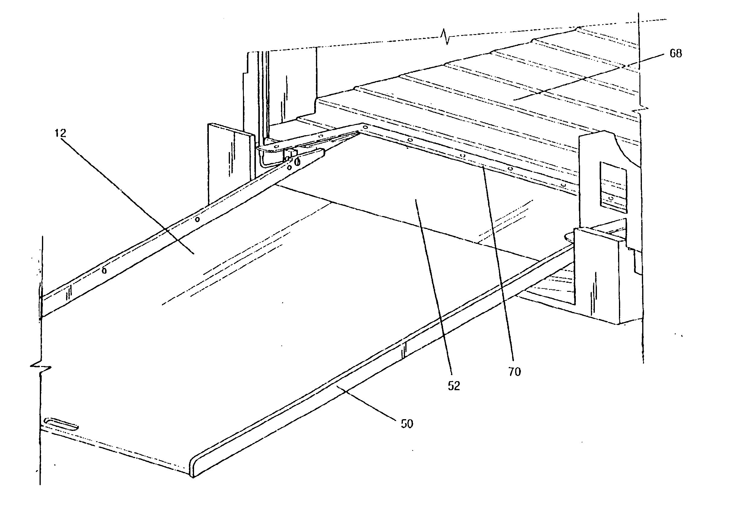
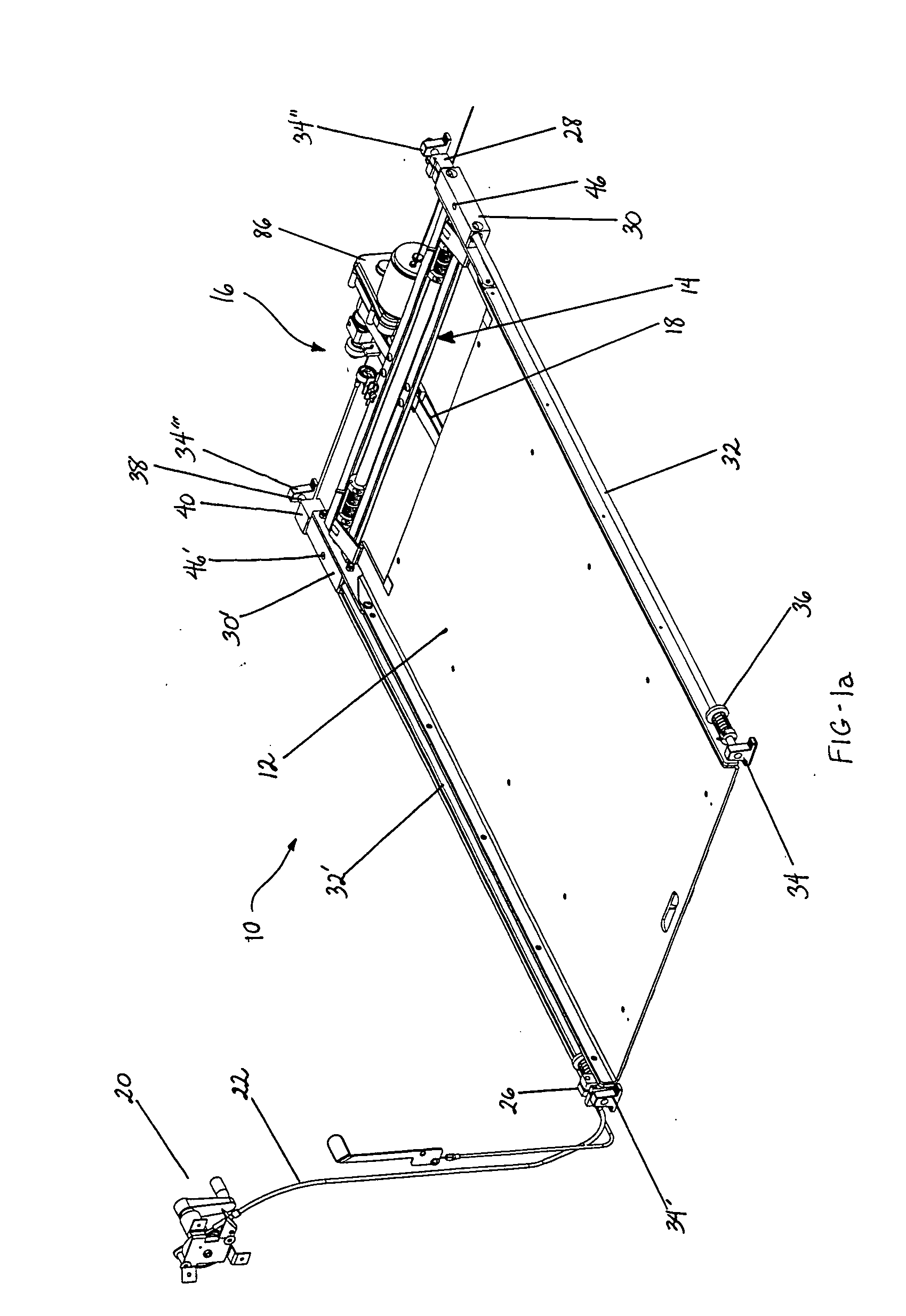
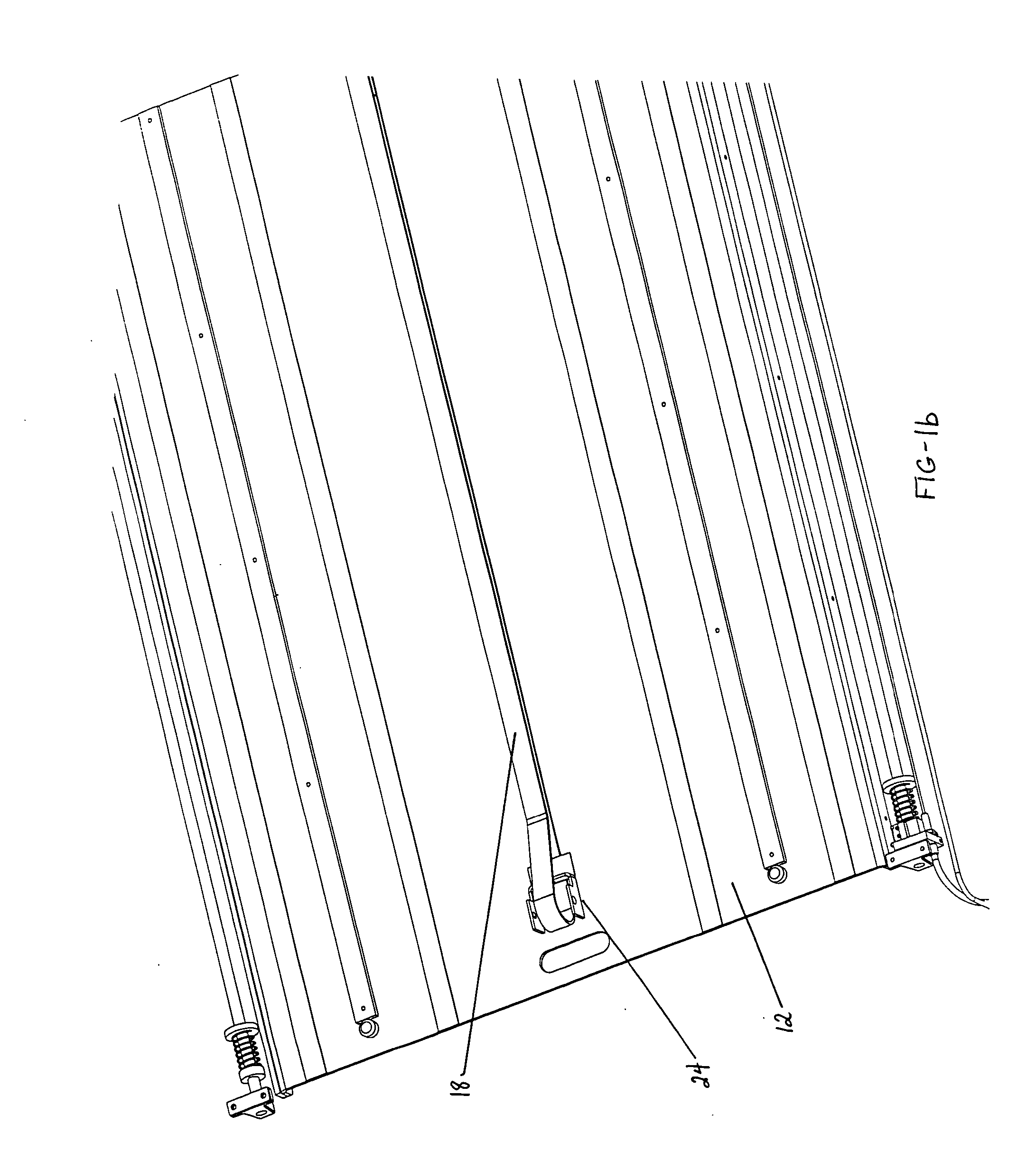
[0057] The present invention is a system and method for deploying and stowing a low-profile ramp incorporated horizontally into the floor of a mobility vehicle to allow a smooth transition between the floor of the vehicle and the ground, or other external surface. The preferred embodiment of the present invention for a retractable ramp system includes a ramp platform, carriage assembly, ramp transition flap, motor and drive belt, mechanical motor release, and manual control capability. The construction of the invention is described first followed by the method of operation.

[0058] As used herein the term "mobility vehicle" refers to any vehicle used to transport disabled individuals, including but not limited to standard-sized vans, mini-vans, buses, trains, and the like. As used herein, the term "distal" refers to those points at a distance from the mobility vehicle, such as the end of the ramp that engages the ground. Conversely, the term "near" refers to points closer to the mobi...


PUM


Abstract

A retractable ramp system 10 for a mobility vehicle. A ramp platform 12 is driven by a reversible motor 86, associated drive pulley 88, and drive belt 18 affixed to a ramp carriage assembly 14. A spring-loaded mechanical release assembly 98 is used to engage the drive pulley to the motor and to disengage the drive pulley from the motor. A manual control assembly is used for manual deployment of the ramp when the drive pulley is disengaged from the motor. Ramp flap 52 provides a transition between ramp platform 12 and a mobility vehicle. Ramp flap is supported by wheels 54 which translate along ramp platform 12. Linear bearing blocks 30 attach to pivot arms 44 of the carriage assembly, which are in turn pivotably attached to ramp platform 12. Linear bearing blocks 30 translate ramp platform 12 along guide shafts 32 during deployment and stowage.

Description

[0001] This application is based on U.S. Provisional Application Serial No. 60 / 443,483 entitled "Low Profile, Slide-Out Ramp Mechanism", filed on Jan. 29, 2003, the teachings of which are incorporated herein by reference.[0002] 1. Field of the Invention (Technical Field)[0003] The present invention relates generally to the field of ramps for facilitating disabled individuals ascent to and descent from a structure, particularly, the present invention relates to the field of retractable ramps used in motorized vehicles for efficient ingress and egress by wheelchair or scooter occupants.[0004] 2. Background Art[0005] Vehicles adapted for mobility-challenged individuals are necessary to provide such individuals the ability to travel in a manner similar to ambulatory passengers. Historically, these vehicles consisted of full-sized vans having an electrical or hydraulic powered wheelchair lift installed on the vehicle to assist wheelchair occupants into and out of the van. These lifts con...

Claims


Application Information

Patent Timeline
IPC IPC(8): B60P1/43
CPCB60P1/431Y10S414/134
Inventor EDWARDS, PAUL H.MALONE, RYAN K.JOHNSON, CHARLES E.
Owner BRAUN THE
Why Eureka
Try Eureka