Connecting corner for knock down racks

a technology of connecting corners and knock-down racks, which is applied in the direction of dismountable cabinets, movable shelf cabinets, mechanical instruments, etc., can solve the problems of reducing freight costs, reducing the ease of assembly of enclosures, and affecting the stability of the enclosur

Inactive Publication Date: 2004-08-12
ERWIN TOMA SUSAN +1
View PDF25 Cites 7 Cited by
  • Summary
  • Abstract
  • Description
  • Claims
  • Application Information

AI Technical Summary

Problems solved by technology

However, consumers complain about the permanent characteristics of the assembled enclosure.
These enclosures are not adjustable without great difficulty and the cost of shipping a fully assembled unit is expensive.
These enclosures reduced freight costs but did not address the issue of ease of assembly.
Consequently, enclosure assembly takes a long time and the parts are cumbersome and difficult to maneuver.
Knocked-down enclosures are easier to use and less expensive to ship, but they do not possess the ease of assembly and simplicity of design.
(b) The assortments of parts are many, cumbersome, and difficult to assemble.
(e) Custom orders take extended time to manufacture, cost more to produce and deliver, and are easily incorrectly communicated and consequently frequently delivered inaccurately.
(f) Incorrect custom orders must be returned to the manufacture for credit and cost the consumer time and money.
The process of waiting for refunds, or credit to be issued, leaves the consumer frustrated, and in spite of everything the end result is no effective and operational rack enclosure, and consequently no solution in sight for their initial packaging problems.

Method used


Image

  • Connecting corner for knock down racks
  • Connecting corner for knock down racks
  • Connecting corner for knock down racks

Examples


Embodiment Construction

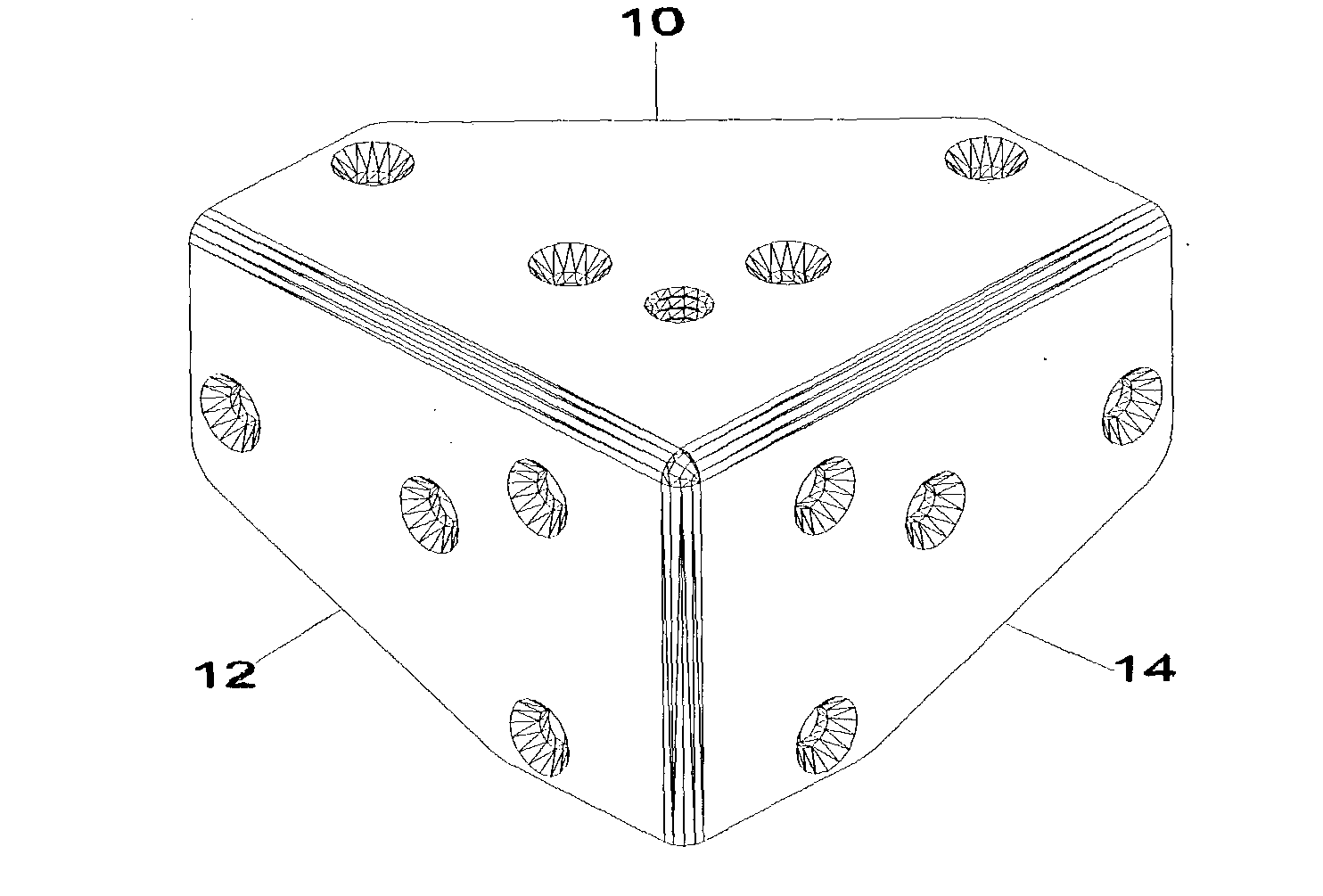
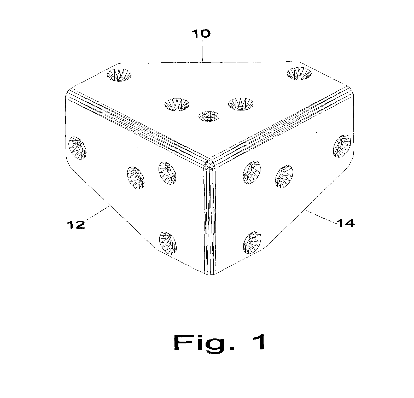
. 1 AND 1A--OUTER EMBODIMENT

[0042] An outer embodiment of the connecting corner of the present invention is illustrated in FIG. 1 (full outer view) and FIG. 1A (detailed outer view). The connecting corner has a solid body of uniform cross section consisting of a solid metal, which is formed or molded. A layer of (black clad finish) plating 56 covers all the surfaces of the corner. In the outer embodiment, the body is made of metal, such as cast aluminum. However, the body can consist of any other material that can be formed or molded without fracturing, such as aluminum, molded plastic, such as polyethylene, polypropylene, rubber, various impregnated or fibrous materials, various plastic material, that can withstand the stress and various weight factors.

[0043] Base 10 of connecting corner has counter sunk hole 16 and hole 18 positioned to match up with holes in one surface of rack rail inserted in left leg rack rail entry slot 42. Counter sunk hole 20 and hole 22 are positioned to m...


PUM


Abstract

The invention pertains to a connecting corner used in assembling metal rack frame enclosures for housing a variety of equipment. A completely assembled rack frame consists of eight connecting corners, three sets of variable length rails (four identically sized rails per set), and ninety-six fasteners. The connecting corner is made of metal. The connecting corner has three legs; base (10), leg (12), and leg (14) with three inner slots; slot (42), slot (44), and slot (46). Each slot accepts two-legged metal rail (58), with industry standard, consistently repetitive hole pattern; hole (60), hole (62), hole (64), and marker (66). Each slot is supported by double-sided overlapping tapered reinforcing ribs; rib (50), rib (52), and rib (54). Rail stop embossment (48) prevents rails in slot (42), slot (44), and slot (46) from making contact with each other. There are four counter sunk holes in each leg of connecting corner. Corner base (10) includes hole (16), hole (18), hole (20), hole (22), and supplemental threaded hole (24). Corner leg (12) includes hole (26), hole (28), hole (30), and hole (32). Corner leg (14) includes hole (34), hole (36), hole (38), and hole (40). These holes match up, and align, with holes in metal rail (58), and fasteners are used to secure each rail in place thus forming a completely assembled rack frame.

Description

[0001] Not ApplicableFEDERALLY SPONSORED RESEARCH[0002] Not ApplicableSEQUENCE LISTING OR PROGRAM[0003] Not ApplicableBACKGROUND OF THE INVENTION--KNOCK-DOWN RACKS[0004] This invention relates to knocked-down racks, specifically to such racks that are used for housing electronic industry standard rack width equipment.[0005] Manufacturers supply the consumer marketplace with equipment enclosures and equipment rack enclosures for housing equipment. Such equipment enclosures and equipment rack enclosures are also supplied to provide a reasonable structure for rack mountable industry standard electronic equipment.[0006] Currently, these enclosures are supplied fully assembled. However, consumers complain about the permanent characteristics of the assembled enclosure. These enclosures are not adjustable without great difficulty and the cost of shipping a fully assembled unit is expensive.[0007] Thereafter, several types of enclosures were established that could ship knocked-down. These e...

Claims


Application Information

Patent Timeline
Patent Type & Authority Applications(United States)
IPC IPC(8): F16B12/50H02B1/01
CPCH02B1/014F16B12/50
Inventor TOMA, DENNIS
Owner ERWIN TOMA SUSAN
Why Eureka
Try Eureka