
Water weighted tarp

a self-weighting, tarpaulin technology, applied in the direction of building components, transportation and packaging, building insulation, etc., can solve the problems of prone to tearing the tarpaulin, jeopardizing the entire tarpaulin, and objects that are not always handy, so as to achieve continuous and uniform water weighting, the effect of not being able to blow away

Inactive Publication Date: 2004-10-07
HORMAN GEORGE A
View PDF20 Cites 15 Cited by
  • Summary
  • Abstract
  • Description
  • Claims
  • Application Information

AI Technical Summary

Benefits of technology

[0026] An advantage of the present invention is that the water ring located around perimeter of tarp is sewn into place and provides continuous and uniform weighting of water that is almost impossible to blow away.
[0028] The advantages and features of the present invention will become better understood with reference to the following more detailed description and claims taken in conjunction with the accompanying drawings, in which like elements are identified with like symbols, and in which:
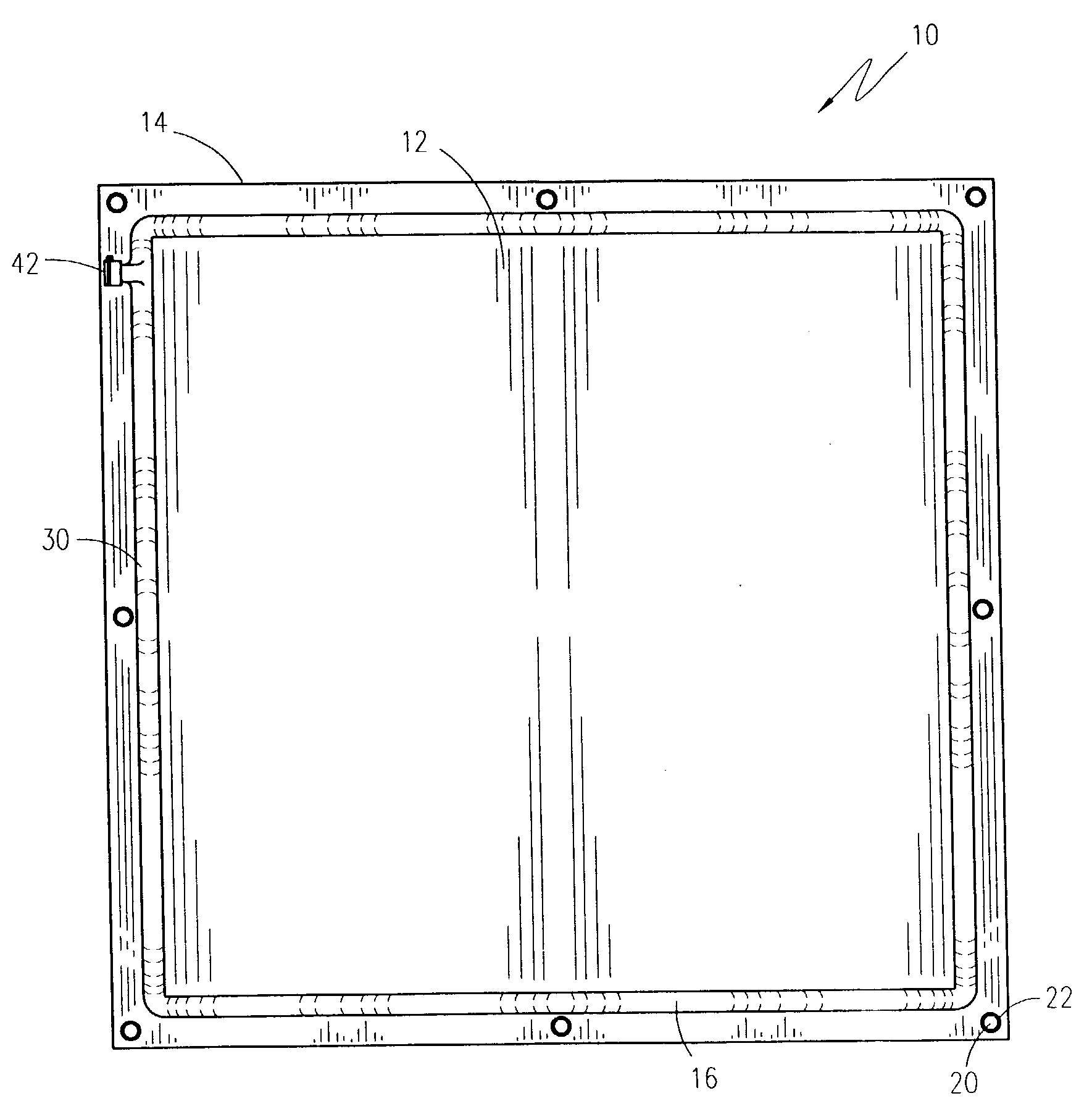
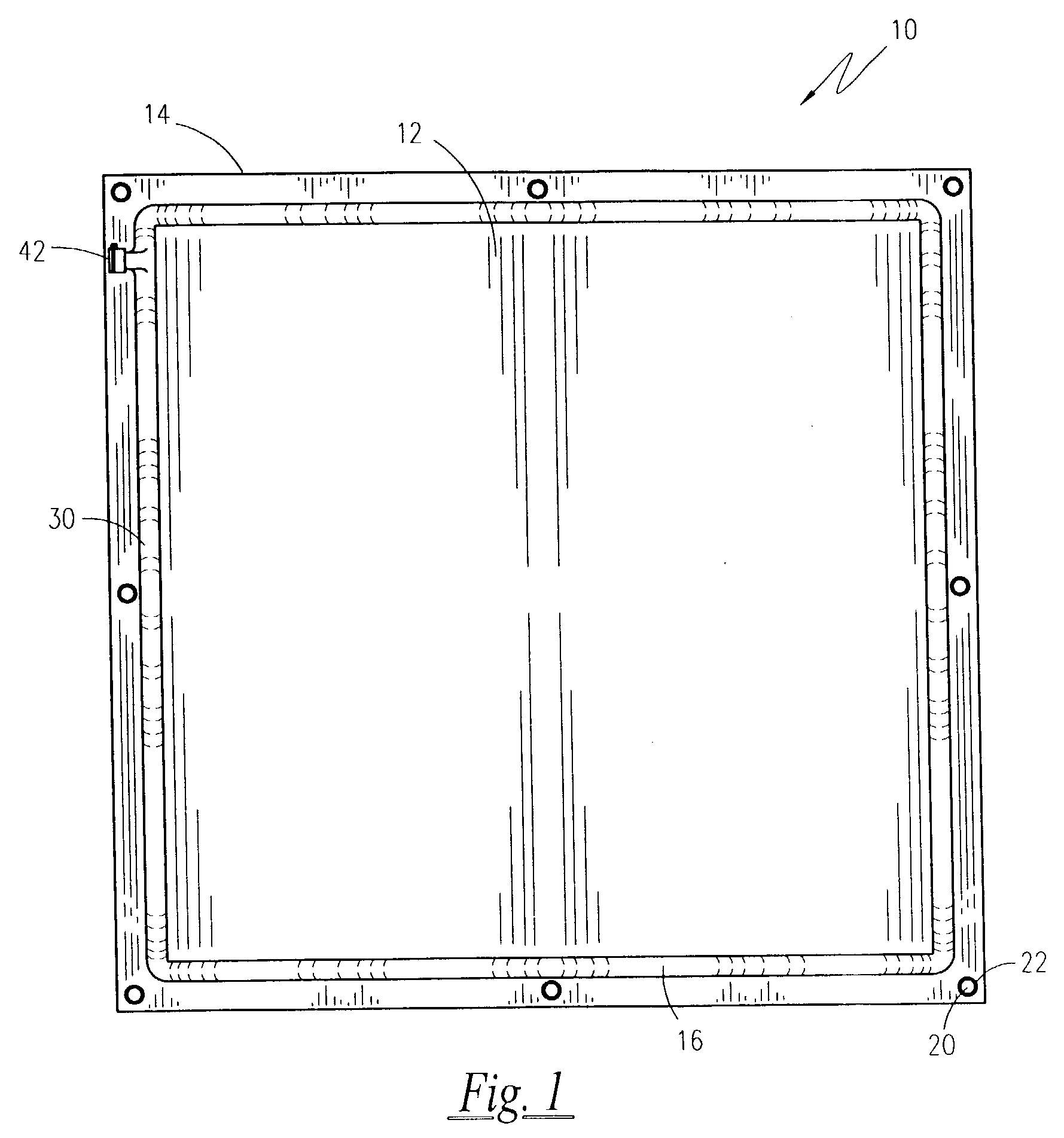
[0029] FIG. 1 is a top plan view of a weighted water tarp according to the preferred embodiment of the present invention;
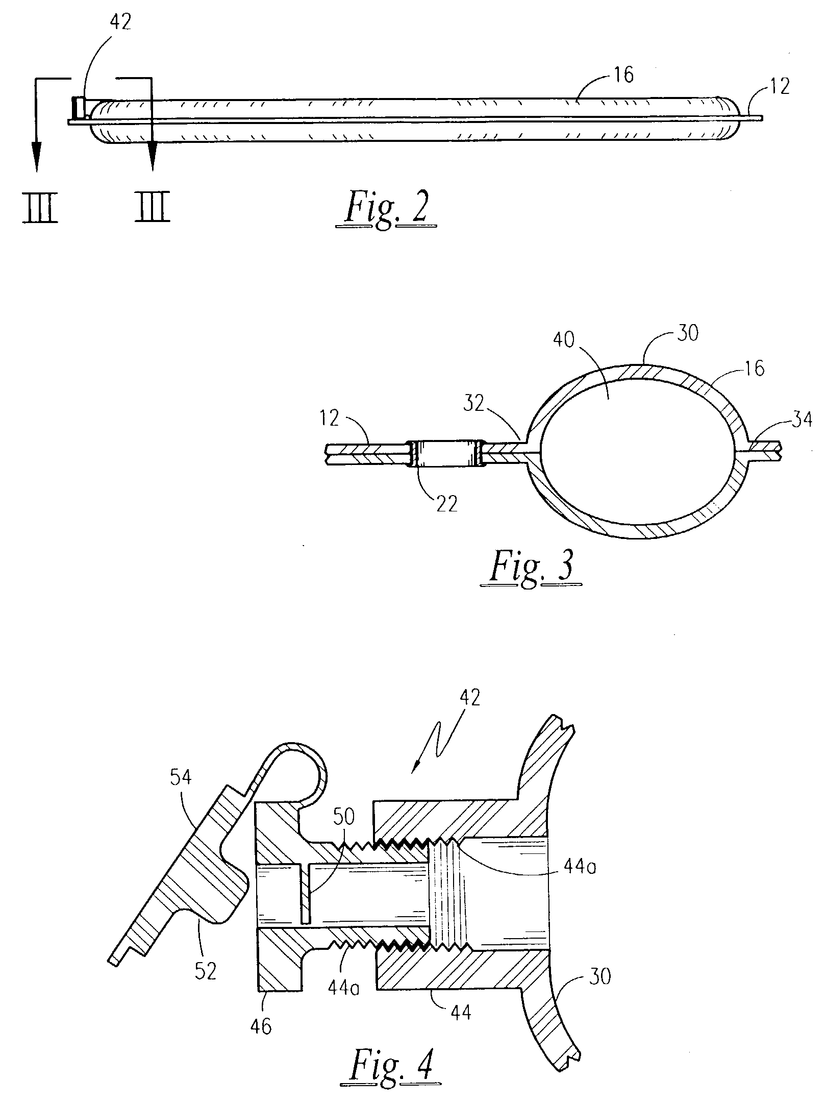
[0031] FIG. 3 partial elevational cross section taken along line III-III of FIG. 2; and; and

Problems solved by technology

However, such objects are not always handy, and if they are, they are prone to tearing the tarpaulin.
Additionally, such weighting is not continuous or uniform around the perimeter and may allow a section of the tarpaulin to be picked up by the wind, thus jeopardizing the entire tarpaulin.

Method used


Image

  • Water weighted tarp
  • Water weighted tarp
  • Water weighted tarp

Examples


Embodiment Construction

of the Figures

[0035] Referring now to FIG. 1-2, a weighted water tarp apparatus 10 is shown, according to the present invention, having a generally flat tarp planar surface 12 anticipated as being of an otherwise conventional material and construction as tarps currently available. Shown here as rectangular in shape, it is envisioned that any geometry could also incorporate the teachings of the present invention. The tarp planar surface 12 is bounded by a peripheral hem 14, and is circumscribed out its outer perimeter by a perimeter tube 16. The peripheral hem 14 is shown forming a plurality of tie-down holes 20, each aligned with conventional metal grommets 22 for added strength and resistance to tearing. The peripheral tube 16 is shown in greater detail in conjunction with FIG. 3, and has a seamless upper tube sidewall 30 terminated at each side in an attachment flange 32. A lower sidewall 34 is affixed to the attachment flanges 32 in a water-tight, sealed manner. Similarly, the lo...


PUM


Abstract

A tarpaulin cover with a water-weighted tube around its perimeter is provided. A three-inch diameter tube is located around the perimeter of the invention just inside of a series of grommets. A fill nozzle that accepts a standard garden hose connection is provided on the perimeter. At the opposite side of the tarpaulin, a release nozzle is provided to aid in the rapid emptying of the invention. When filled with water, the invention is almost impossible to blow away in high winds. It is intended to eliminate the usage of rocks, logs and other materials that are commonly used to hold tarpaulins down.

Description

[0001] The present invention was first described in Disclosure Document Registration 516,204 filed on Jul. 31, 2002 under 35 U.S.C. .sctn.122 and 37 C.F.R. .sctn.1.14. There are no previously filed, nor currently any co-pending applications, anywhere in the world.[0002] 1. Field of the Invention[0003] The present invention relates generally to self-weighted tarps and, more particularly, to a tarp incorporating an integral water retaining conduit formed along a perimeter thereof which includes a one-way water influx valve and a water release valve.[0004] 2. Description of the Related Art[0005] As is well known in the art, Tarpaulins or tarps, are commonly used to cover items and material located outdoors thus affording such objects protection from the environment. The list of objects covered by tarpaulins includes topsoil, mulch, firewood, building materials, outdoor furniture and the like. Should the tarpaulin be used in even light winds, it must be secured to prevent it from blowin...

Claims


Application Information

Patent Timeline
IPC IPC(8): A01G13/02E04B1/66E04G21/28
CPCE04B1/66E04G21/28E04G2021/248
Inventor HORMAN, GEORGE A.
Owner HORMAN GEORGE A
Learn More