Safety device for firearms with a firing pin lock

a safety device and firearm technology, applied in the direction of safety arrangement, weapons, weapons, etc., can solve the problems of inability to fire shots, inability to release safety wing unintentionally from the secure position, and inability to exclude inadvertent release of safety during normal use of weapons

Inactive Publication Date: 2004-10-28
PRECHTL GOTTFRIED
View PDF20 Cites 1 Cited by
  • Summary
  • Abstract
  • Description
  • Claims
  • Application Information

AI Technical Summary

Benefits of technology

0006] The present invention provides a device wherein the safety shaft is arrested in a position in that secures the weapon. The safety shaft, while secur

Problems solved by technology

A shot however cannot be fired, since the lower part of the safety shaft has not unlocked the trigger.
These safety devices, however, suffer from the disadvantage that the safety wing can be unintentionally pushed forward from the secure position, especially while climbing an elevated blind, and whe

Method used


Image

  • Safety device for firearms with a firing pin lock
  • Safety device for firearms with a firing pin lock
  • Safety device for firearms with a firing pin lock

Examples


Embodiment Construction

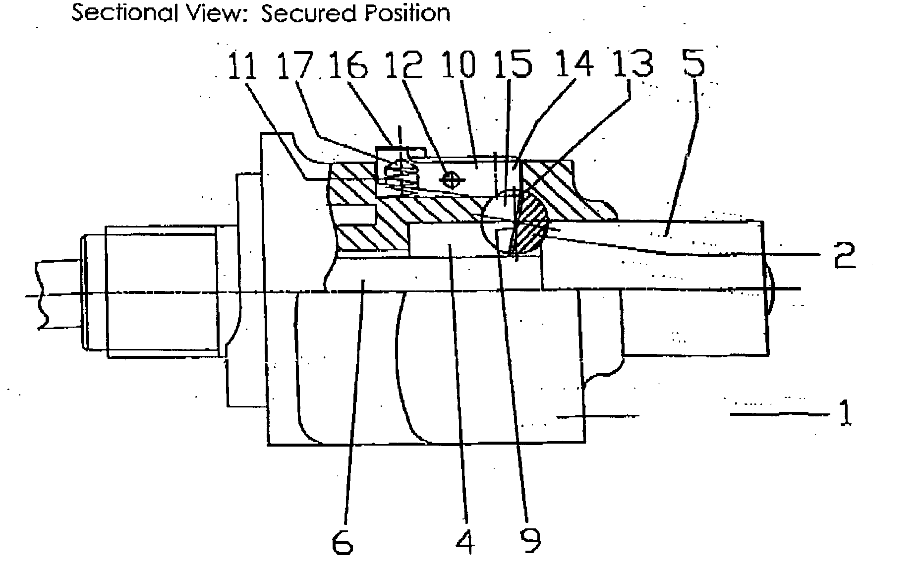
[0016] The invention is being described further, by example of the widespread firing pin lock type "Dakota". The arresting of the safety shaft here is easily achieved. Notably, this invention can be implemented or other locks of similar design, since a particular advantage of the present invention is that it can be fitted to already existing locks.

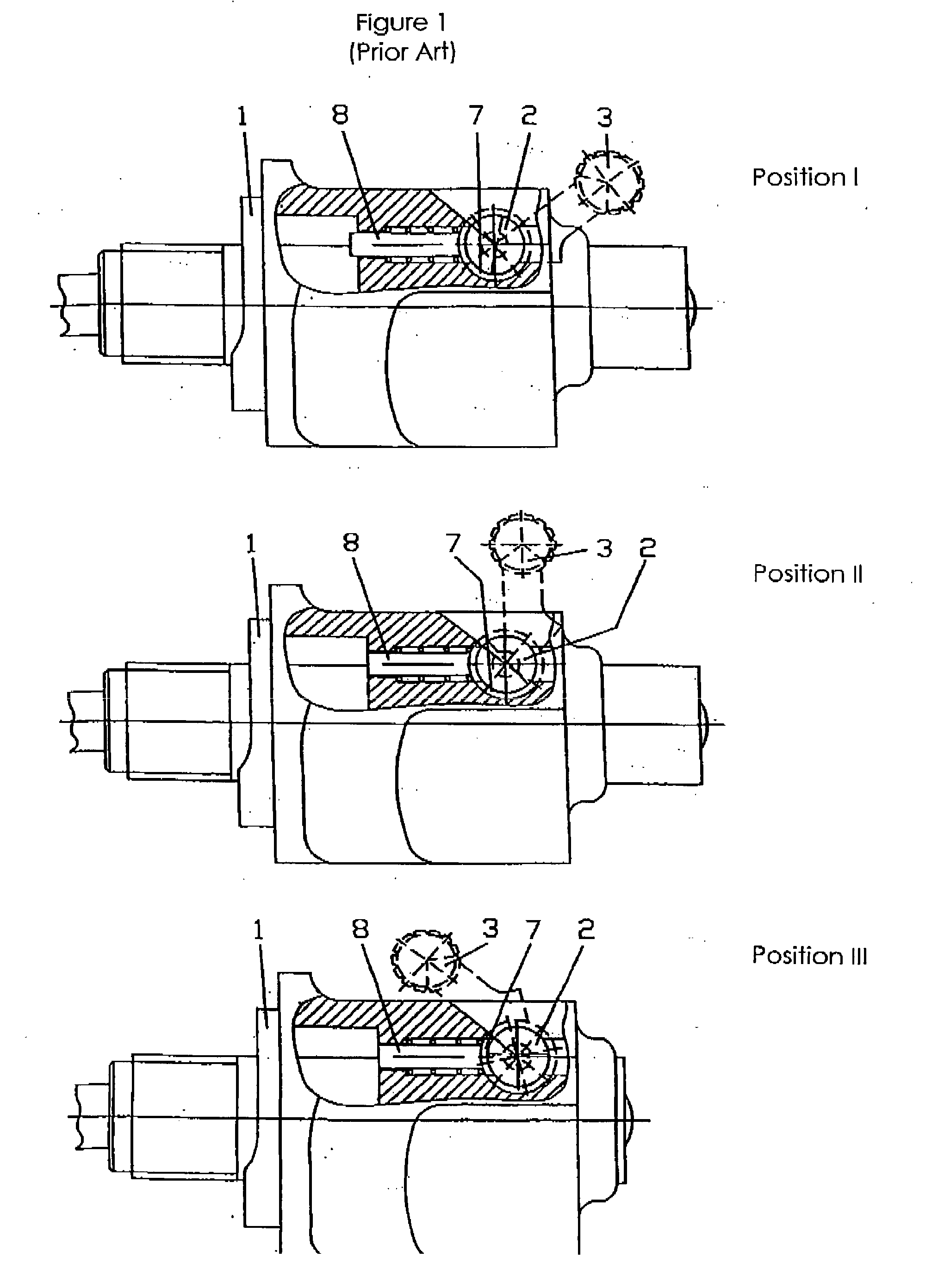
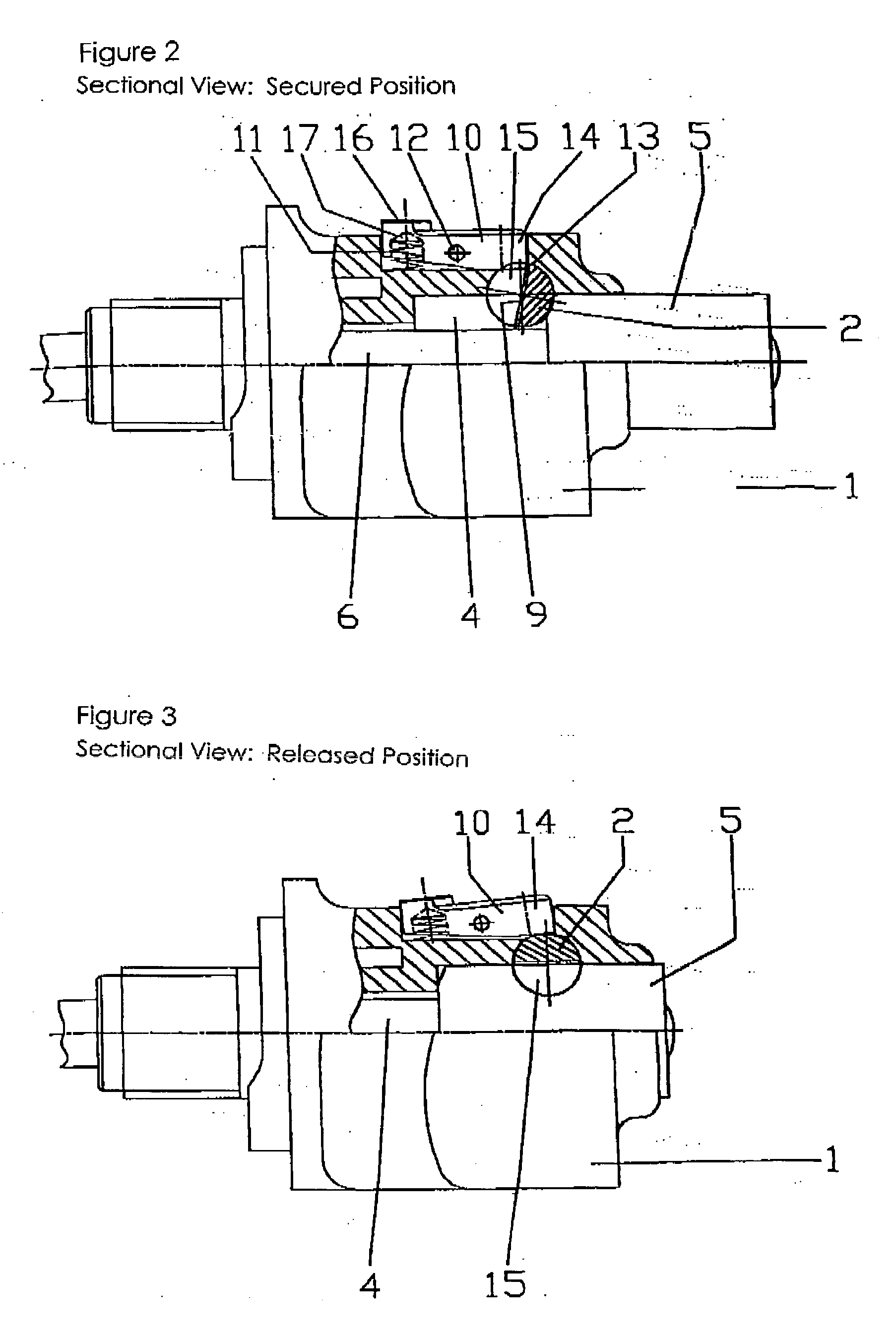
[0017] The firing pin lock 1 in FIG. 1 in top view is provided with a safety shaft 2. The safety shaft 2 is situated in the lock 1 and is turned by means of the safety wing 3 affixed to it. In the shown position I of the safety wing 3 the weapon is completely secured. The safety shaft 2 is swiveled into the firing pin bore 4 (FIG. 2) and abuts to the nut / mother of the firing pin 5. Thereby the firing pin 6 is blocked. At the same time the pin 8 is pushed forward through the cam area 7 into a dead end bore existing close by the socket, which is not shown in detail, and the lock 1 is thereby secured against turning. The position of the pin 8...


PUM


Abstract

The present invention provides a device wherein the safety is arrested in a position in that secures the weapon. The safety shaft, while securing the weapon, is fixed in such a way that any force applied to the safety wing cannot result in a movement of either the safety wing or the safety shaft.

Description

[0001] This invention relates to a safety device for firearms with a firing pin lock to prevent the unintended unlocking of the firearm wherein the safety device comprises a rotatable safety shaft connected to the firing pin lock with locking surfaces. The safety shaft is adjustable in at least two positions for locking of at least the firing pin.BACKGROUND OF INVENTION[0002] Hunting rifles and other firearms are commonly equipped with safety devices, which prevent unintended unlocking of the firearm. These safety devices secure the trigger so that it cannot be actuated. A safety device where the trigger is secured, is described in DE 78 449. Other safety devices function by securing the firing pins.[0003] Safety devices where both the trigger as well as the firing pin or bolt are secured are also known--the art. An example of such a safety device is described in EP 0 143 625 B1. A safety shaft, which is affixed at the firing pin lock, can be set to three positions. The adjustment i...

Claims


Application Information

Patent Timeline
IPC IPC(8): F41A17/70
CPCF41A17/70
Inventor PRECHTL, GOTTFRIED
Owner PRECHTL GOTTFRIED
Why Eureka
Try Eureka