
Display device including a touch sensing unit and method of manufacturing the same

a touch sensing unit and display device technology, applied in the field of display devices, can solve the problems of uneven or non-uniform layer thickness, complicated process, and complicated manufacturing process of such display devices, and achieve the effect of reducing or eliminating the possibility of layers, reducing or eliminating the possibility of defects, and reducing or eliminating the possibility of leakage and subsequent delamination

Active Publication Date: 2019-07-23
SAMSUNG DISPLAY CO LTD
View PDF18 Cites 4 Cited by
  • Summary
  • Abstract
  • Description
  • Claims
  • Application Information

AI Technical Summary

Benefits of technology

The invention provides a display device and method of manufacturing it that reduces or eliminates certain defects, such as delamination of layers and cuts or scratches on touch signal lines. This is achieved by using a thicker photoresist layer in the inclined parts of the process, which prevents leakage of organic material and results in a more stable pattern. Overall, the invention improves the manufacturing process of display devices and increases production efficiency.

Problems solved by technology

Manufacture of such display devices is a complicated process requiring deposition of multiple layers of sensitive material and photoresist with tight tolerances.
Incorporation of touch sensing lines for touch units has further complicated the process.
To create the requisite structural components in such devices, layers are often required to be deposited along inclined surfaces, which could result in uneven or non-uniform layer thickness.
One of the problems that can result from deposition of non-uniform layers in OLEDs is delamination of layers due to leakage of organic material along the inclined surfaces during the etching process for forming the touch lines in the display device.

Method used


Image

  • Display device including a touch sensing unit and method of manufacturing the same
  • Display device including a touch sensing unit and method of manufacturing the same
  • Display device including a touch sensing unit and method of manufacturing the same

Examples


Embodiment Construction

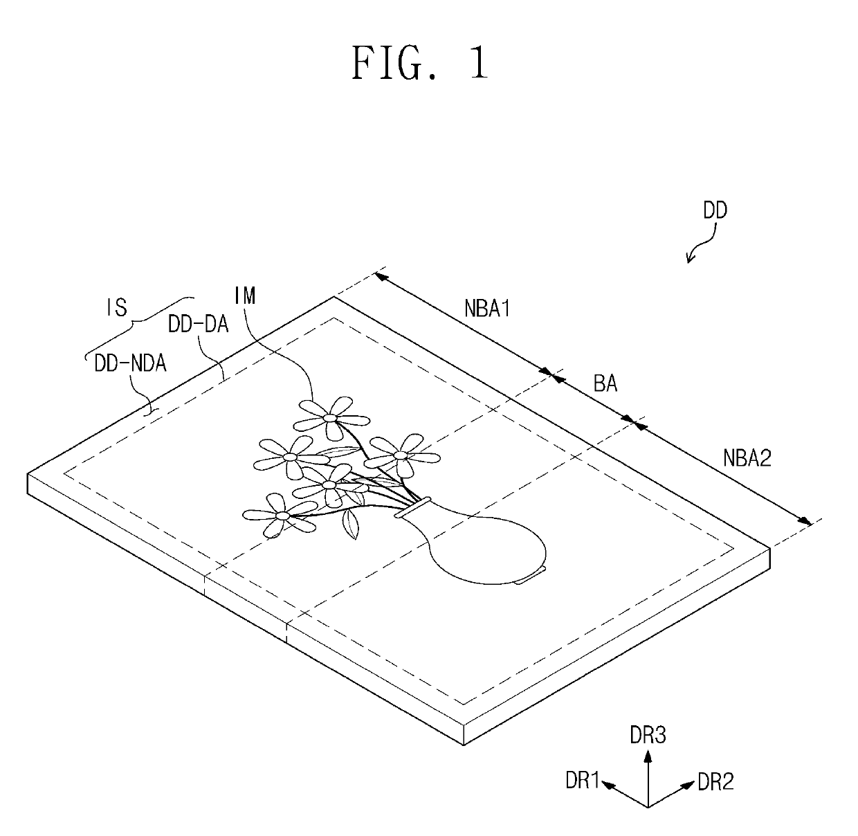
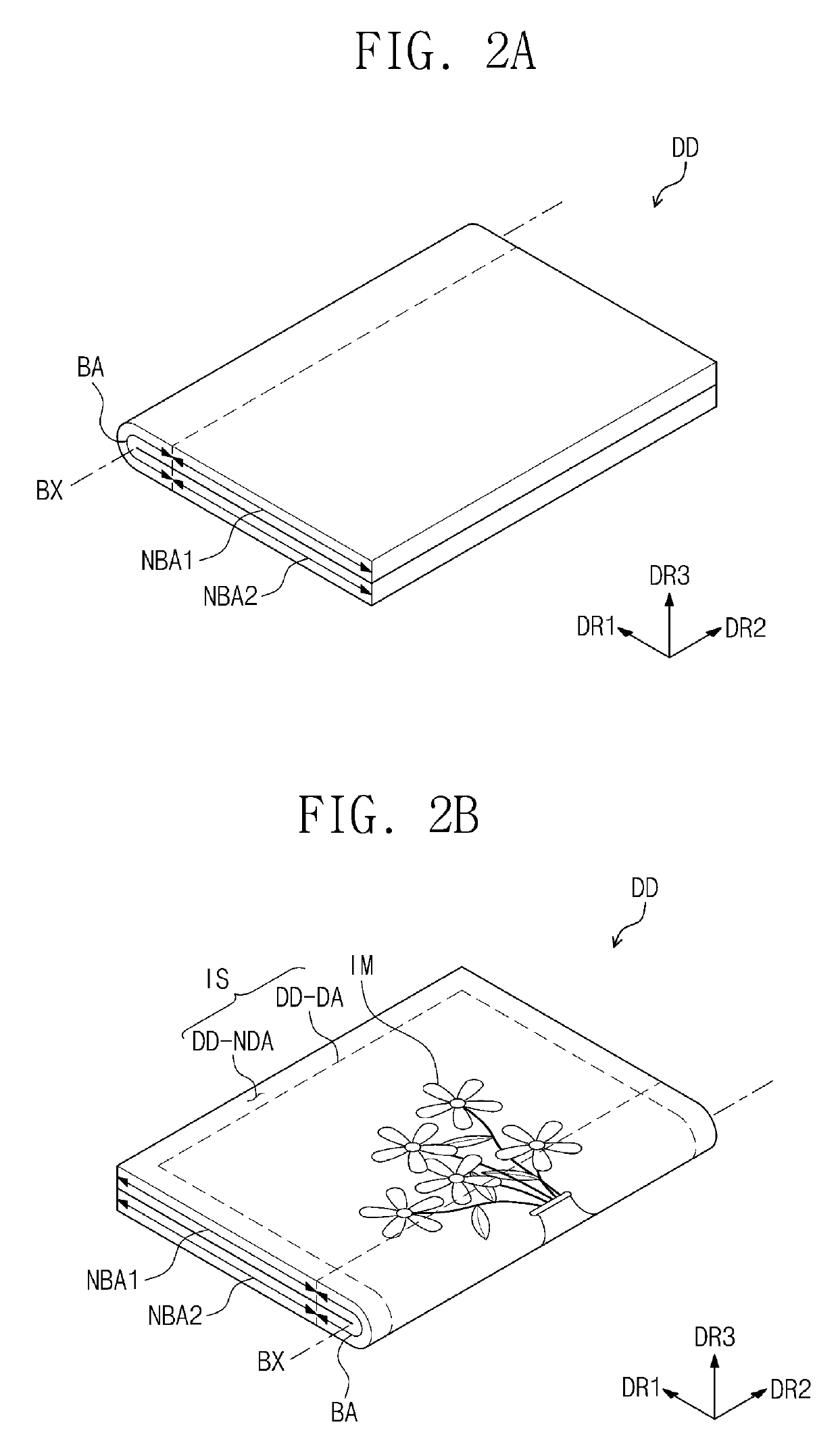
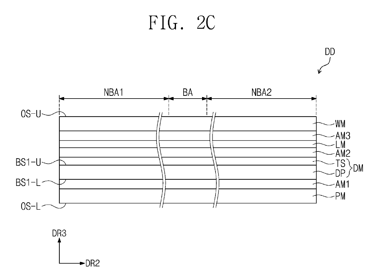
[0050]In the following description, for the purposes of explanation, numerous specific details are set forth in order to provide a thorough understanding of various exemplary embodiments. It is apparent, however, that various exemplary embodiments may be practiced without these specific details or with one or more equivalent arrangements. In other instances, well-known structures and devices are shown in block diagram form in order to avoid unnecessarily obscuring various exemplary embodiments.

[0051]In the accompanying figures, the size and relative sizes of layers, films, panels, regions, etc., may be exaggerated for clarity and descriptive purposes. Also, like reference numerals denote like elements.

[0052]When an element or layer is referred to as being “on,”“connected to,” or “coupled to” another element or layer, it may be directly on, connected to, or coupled to the other element or layer or intervening elements or layers may be present. When, however, an element or layer is re...


PUM


Abstract

A display device including a substrate having a display area and a peripheral area defined outside the display area, a circuit layer disposed on the substrate, a device layer disposed on the display area, an encapsulation layer covering the device layer, a touch sensing unit including at least one touch insulating layer disposed on the encapsulation layer, touch electrodes disposed on the encapsulation layer, and touch signal lines connected to the touch electrodes, a first section disposed in the peripheral area and including a first part having a first thickness, a second part having a second thickness less than the first thickness and overlapping the touch signal lines, and an intermediate part connecting the first part and the second part and being inclined, and a first thickening pattern overlapping at least the intermediate part.

Description

CROSS-REFERENCE TO RELATED APPLICATION[0001]This application claims priority from and the benefit of Korean Patent Application No. 10-2016-0097477, filed on Jul. 29, 2016, which is hereby incorporated by reference for all purposes as if fully set forth herein.BACKGROUNDField[0002]The invention relates generally to a display device and a method of manufacturing the same, and, more particularly, to a display device and method of manufacturing the same that reduces or eliminates the possibility of certain defects occurring in the patterning process of one or more touch lines in the display device.Discussion of the Background[0003]Various display devices for a multimedia device, such as a television set, a mobile phone, a tablet computer, a navigation unit, a game unit, and so on, have been developed. As an input device for the display devices, a keyboard or a mouse is widely used. In recent years, a touch sensing unit is used as the input device of the display devices, which often use ...

Claims


Application Information

Patent Timeline
Patent Type & Authority Patents(United States)
IPC IPC(8): H01L27/32G06F3/044G06F3/041G06F1/16H01L51/10H01L51/00H01L27/12H01L51/52H10K99/00
CPCH01L27/323G06F1/1652G06F3/044G06F3/0412G06F3/0416H01L51/0023H01L51/107H01L51/5256G06F2203/04103G06F2203/04112H01L27/12H01L27/3246H01L27/3258H01L27/3269H10K59/40H10K59/122H10K59/8731H10K59/88G06F3/0443G06F3/0446G06F3/04164H10K59/124H10K59/38H10K59/131H10K71/621H10K59/1201H10K10/88H10K50/8445H10K59/13
Inventor PARK, YONG-HWANKIM, MIYOUNGKIM, JONGSEOK
Owner SAMSUNG DISPLAY CO LTD
Learn More