Motion vector coding method and motion vector decoding method

a technology of motion vector and coding method, which is applied in the field of motion vector coding method and motion vector decoding method, can solve the problem of no efficient coding method of determined motion vector

Active Publication Date: 2004-11-04
TAGIVAN II
View PDF6 Cites 114 Cited by
  • Summary
  • Abstract
  • Description
  • Claims
  • Application Information

AI Technical Summary

Benefits of technology

[0016] Accordingly, even when a block has a plurality of motion vectors pointing in the same direction (forward or backward), the method for coding the motion vectors can be unified, and the coding efficiency of the motion vectors can be improved.
[0018] Accordingly, the motion vector which is coded by the motion vector coding method of the present invention can be correctly decoded.

Problems solved by technology

In the conventional motion vector coding method, even if the neighboring blocks in a B-picture respectively have two motion vectors toward the preceding reference pictures or two motion vectors toward the following reference pictures, there is no definite and unified method of determining which one of these two vectors should be used as a predicted vector, and thus there is no efficient coding method of the determined motion vector.

Method used


Image

  • Motion vector coding method and motion vector decoding method
  • Motion vector coding method and motion vector decoding method
  • Motion vector coding method and motion vector decoding method

Examples


first embodiment

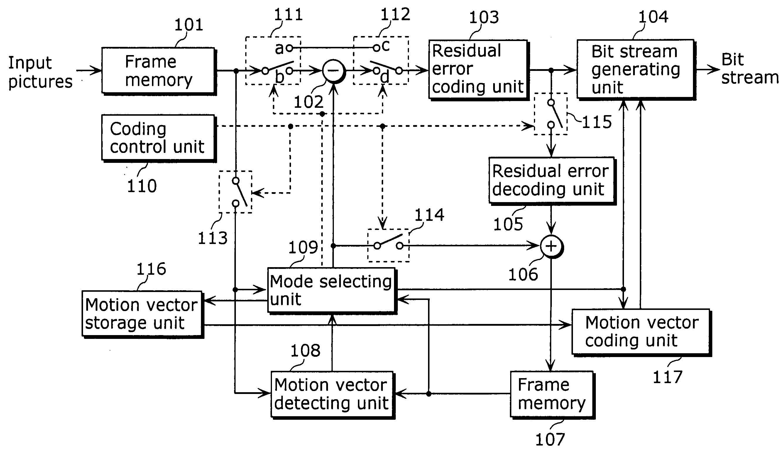
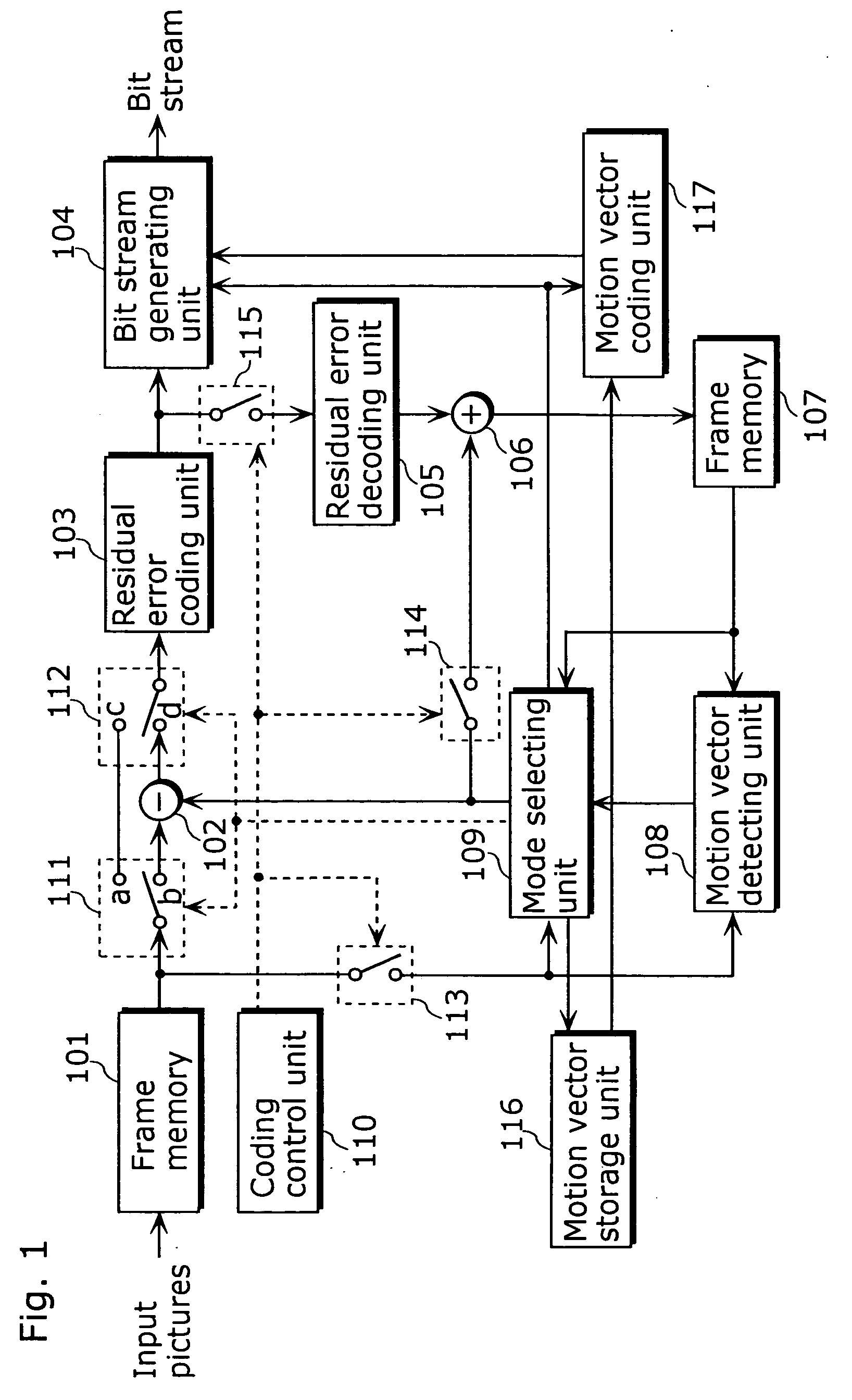
[0043] The first embodiment of the present invention will be explained below with reference to the figures. FIG. 1 is a block diagram of the picture coding apparatus for coding motion vectors as a part of picture coding, including a frame memory 101, a difference calculating unit 102, a residual error coding unit 103, a bit stream generating unit 104, a residual error decoding unit 105, an addition unit 106, a frame memory 107, a motion vector detecting unit 108, a mode selecting unit 109, a coding control unit 110, switches 111.about.115, a motion vector storage unit 116 and a motion vector coding unit 117.

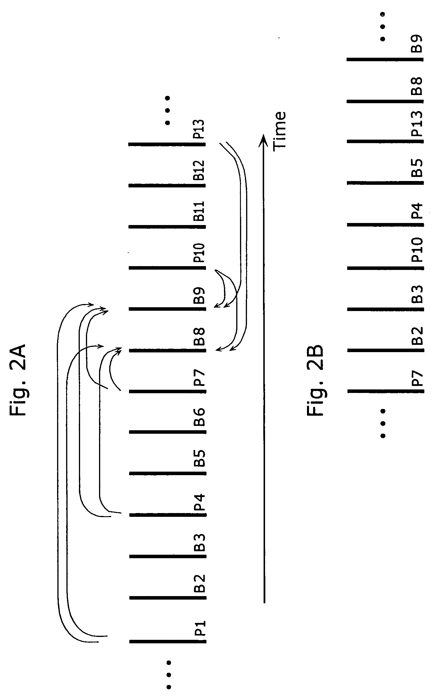
[0044] Pictures are inputted to the frame memory 101 on picture-by-picture basis in display order. FIG. 2A shows the order of inputting pictures into the frame memory 101. In FIG. 2A, vertical lines show pictures, and an alphabet and a number at the lower right of each picture respectively indicate a picture type (P indicates a P-picture and B indicates a B-picture) and a picture...

second embodiment

[0085] The second embodiment of the present invention will be explained below with reference to FIG. 9. FIG. 9 is a block diagram of the picture decoding apparatus for decoding motion vectors as a part of picture decoding, including a bit stream analyzing unit 701, a residual error decoding unit 702, a mode decoding unit 703, a motion compensation decoding unit 705, a motion vector storage unit 706, a frame memory 707, an addition unit 708, switches 709 and 710, and a motion vector decoding unit 711.

[0086] The input order of pictures in the bit stream is same as that shown in FIG. 2B. Decoding processing of the picture B8 will be explained below step by step.

[0087] The bit stream of the picture B8 is inputted to the bit stream analyzing unit 701. The bit stream analyzing unit 701 extracts various types of data from the inputted bit stream. Here, various types of data include mode selection information and motion vector information. The extracted mode selection information is outputt...


PUM


Abstract

The present invention improves efficiency of coding motion vectors when a current block is coded using a plurality of motion vectors. A motion vector coding unit (117) codes a motion vector inputted from a motion vector detecting unit (108). A motion vector for each current block is coded based on a difference between the motion vector and a predicted vector obtained from motion vectors for previously coded neighboring blocks. The predicted vector is generated by one of the following processing: (A) the motion vectors which refer to the same picture are selected from among the motion vectors for the neighboring blocks so as to generate the predicted vector; (B) the motion vectors for the respective neighboring blocks are ordered in the predetermined order, and the motion vectors of the same order rank are selected from the ordered motion vectors so as to generate the predicted vector; and (C) the predicted vector for the second motion vector of the current block shall be the first motion vector, and if the second motion vector and the first motion vector refer to different pictures, the first motion vector is scaled according to the temporal distance between the pictures so as to generate the predicted vector.

Description

[0001] The present invention relates to methods for coding and decoding motion vector information in coding and decoding moving pictures using inter picture prediction coding.[0002] Generally in moving picture coding, information amount is compressed by suppressing the spatial and temporal redundancies that exist within moving pictures. As a method of suppressing the temporal redundancies, inter picture prediction coding is used. In the inter picture prediction coding, for coding a current picture, pictures temporally preceding or following the current picture are used as reference pictures. The motion of the current picture from the reference pictures is detected, and the difference between the picture obtained by motion compensation and the current picture is calculated. Then, the spatial redundancies are eliminated from this difference, so as to compress the information amount of the moving pictures.[0003] In the conventional moving picture coding method according to the MPEG-4 s...

Claims


Application Information

Patent Timeline
Patent Type & Authority Applications(United States)
IPC IPC(8): H03M7/36H04N19/51H04N19/105H04N19/124H04N19/134H04N19/139H04N19/176H04N19/189H04N19/196H04N19/423H04N19/46H04N19/463H04N19/50H04N19/503H04N19/513H04N19/52H04N19/523H04N19/577H04N19/70
CPCH04N7/50H04N19/52H04N19/176H04N19/573H04N19/513H04N19/61H04N19/517H04N19/51
Inventor KONDO, SATOSHIKADONO, SHINYAHAGAI, MAKOTOABE, KIYOFUMI
Owner TAGIVAN II
Why Eureka
Try Eureka