Piston pump

a technology of piston pump and piston plate, which is applied in the direction of engine diaphragm, positive displacement liquid engine, liquid fuel engine, etc., can solve the problems of large known vehicle brake system, large known brake system, and increased manufacturing cos

Inactive Publication Date: 2004-11-25
ROBERT BOSCH GMBH
View PDF5 Cites 36 Cited by
  • Summary
  • Abstract
  • Description
  • Claims
  • Application Information

AI Technical Summary

Problems solved by technology

Because of the pressure damper, the known vehicle brake system is quite large and it req

Method used


Image

  • Piston pump
  • Piston pump
  • Piston pump

Examples


Embodiment Construction

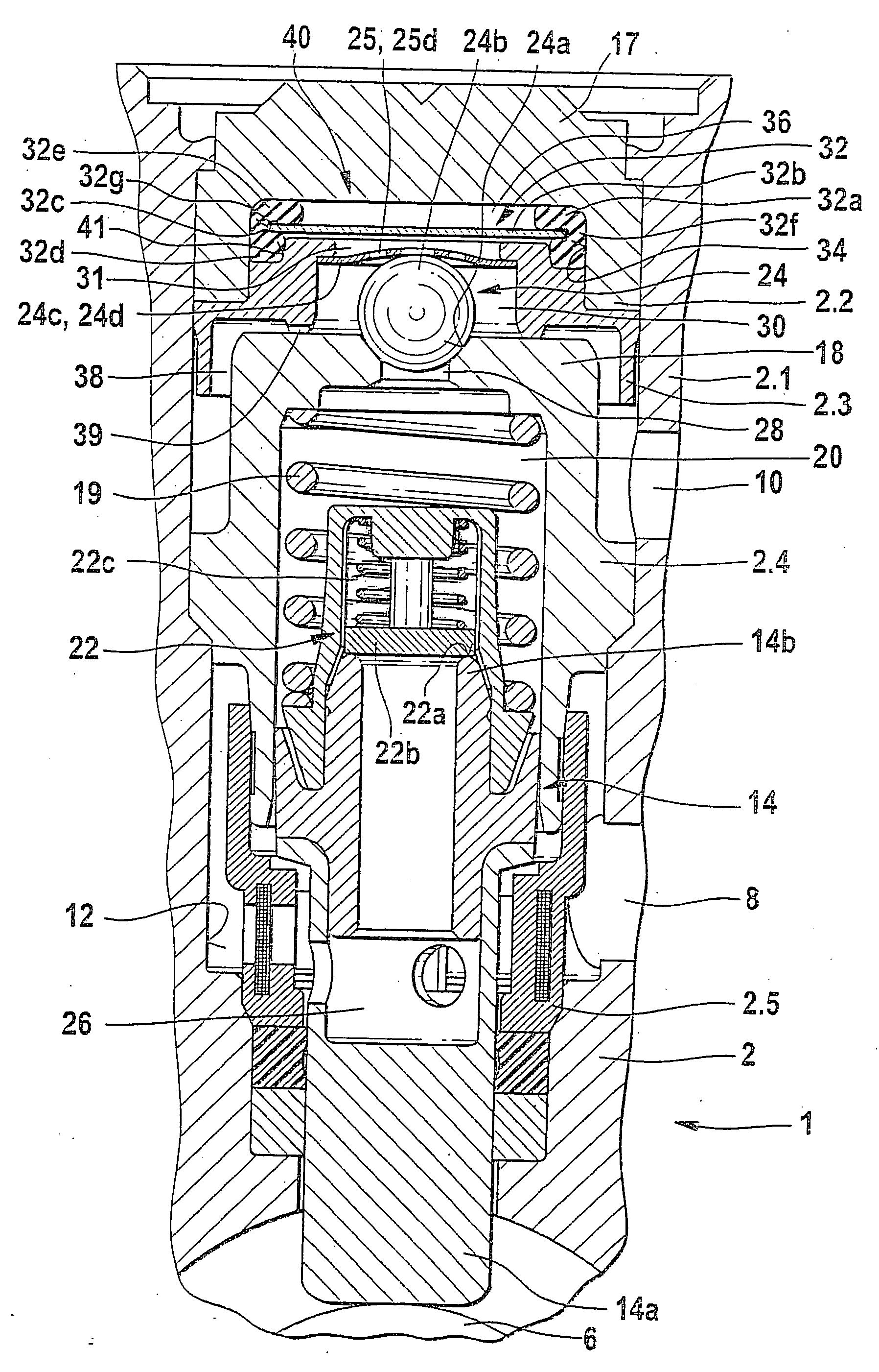
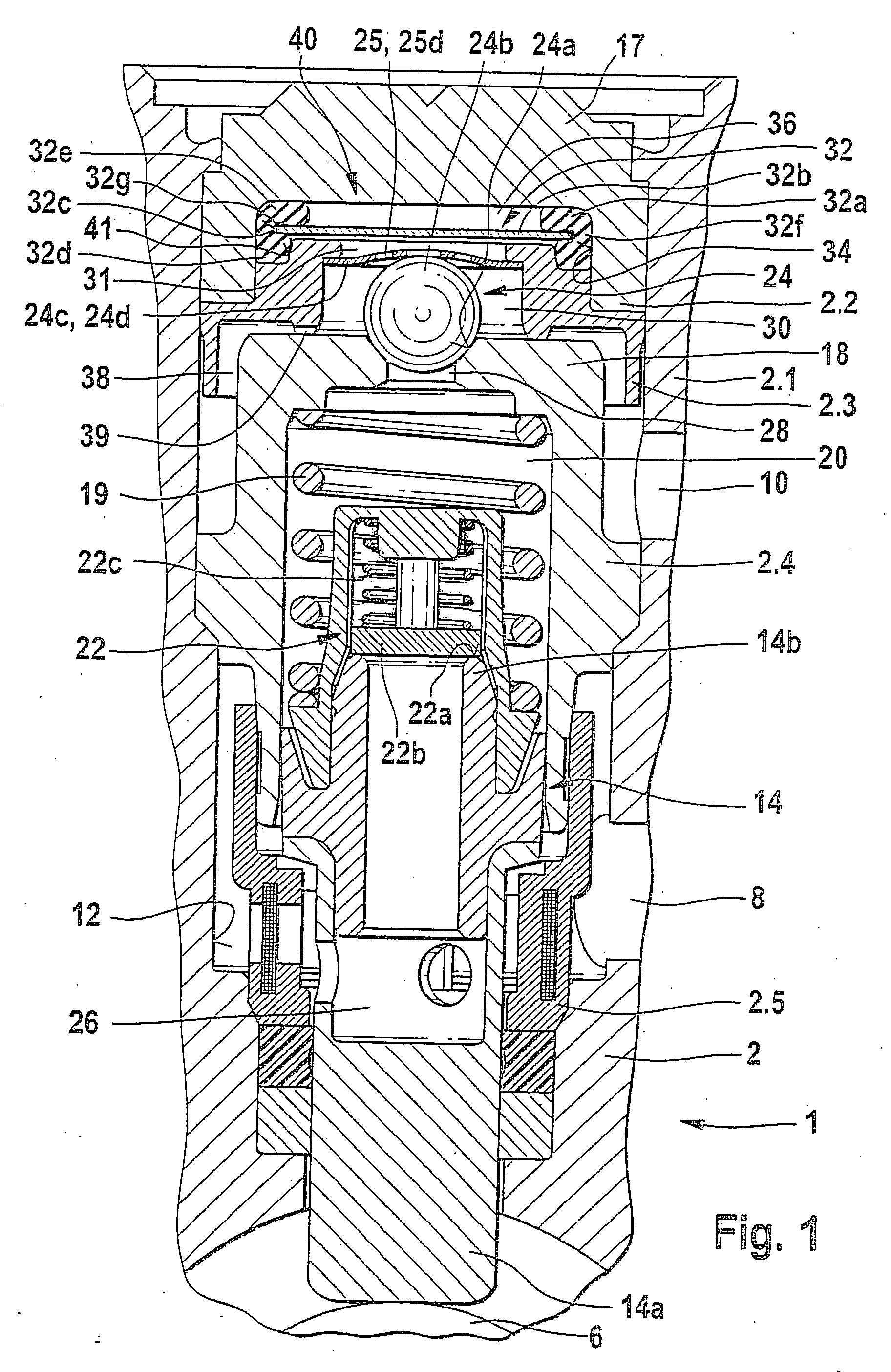
[0016] The piston pump is particularly provided as a pump in a brake system of a vehicle and is used to control the pressure in wheel brake cylinders. Depending on the type of brake system, these brake systems are referred to by the abbreviations ABS, TCS, ESP, or EHB. In the brake system, the pump is used, for example, to return brake fluid from one or more wheel brake cylinders to a master cylinder (ABS) and / or for supplying brake fluid from a reservoir into one or more wheel brake cylinders (TCS, ESP, or EHB). The pump is required, for example, in a brake system with a wheel slip regulation (ABS or TCS) and / or in a brake system used as a steering aid (ESP) and / or in an electrohydraulic brake system (EHB). Wheel slip regulation (ABS or TCS) can, for example, prevent the wheels of the vehicle from locking when powerful pressure is exerted on the brake pedal during a braking maneuver (ABS) and / or can prevent the driven wheels of a vehicle from spinning when powerful pressure is exer...


PUM


Abstract

A piston pump for brake systems the region of the outlet valve is provided with a pressure chamber an opposing chamber, and a flexible wall that divides the pressure chamber from the opposing chamber. The flexible wall has an elastically resilient diaphragm that is supported in an elastically flexible body.

Description

PRIOR ART[0001] The invention relates to a piston pump according to the preamble to claim 1. The piston pump is particularly intended for a hydraulic slip-controlled vehicle brake system.[0002] The German patent application DE 42 26 646 A1 has disclosed a hydraulic vehicle brake system with a pump, in which a pressure damper is provided downstream of an outlet check valve of the pump. In order for the pressure damper provided in the pressure line to have an action of sufficient magnitude, this pressure damper must be provided with correspondingly large dimensions. Because of the pressure damper, the known vehicle brake system is quite large and it requires an increased manufacturing cost. When the brake pedal is actuated, part of the pressure fluid displaced by the action of the driver's foot is forced into the pressure damper. Because the pressure damper must be relatively large to achieve an effect of sufficient magnitude, a relatively large amount of pressure fluid must be displa...

Claims


Application Information

Patent Timeline
IPC IPC(8): B60T8/40F04B1/04F04B53/10F04B11/00F16J3/02
CPCB60T8/4031F04B1/0404F04B11/0016
Inventor SCHEPP, RENEMARQUARDT, WERNER-KARLSCHULLER, WOLFGANGFEINAUER, JOCHENFOERCH, DIRK
Owner ROBERT BOSCH GMBH
Why Eureka
Try Eureka