

Standoff/mask structure for electrical interconnect
a technology of standoff/mask structure and electrical interconnection, which is applied in the direction of conductive pattern formation, transportation and packaging, containers, etc., can solve the problems of difficult to reliably and efficiently mechanically and electrically interconnect circuit structures
- Summary
- Abstract
- Description
- Claims
- Application Information
AI Technical Summary
Problems solved by technology
Method used
Image

Examples
Embodiment Construction
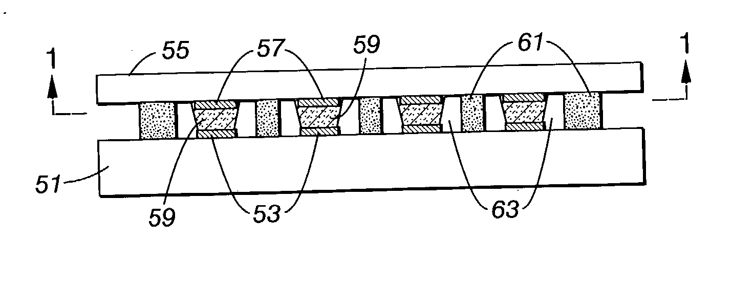
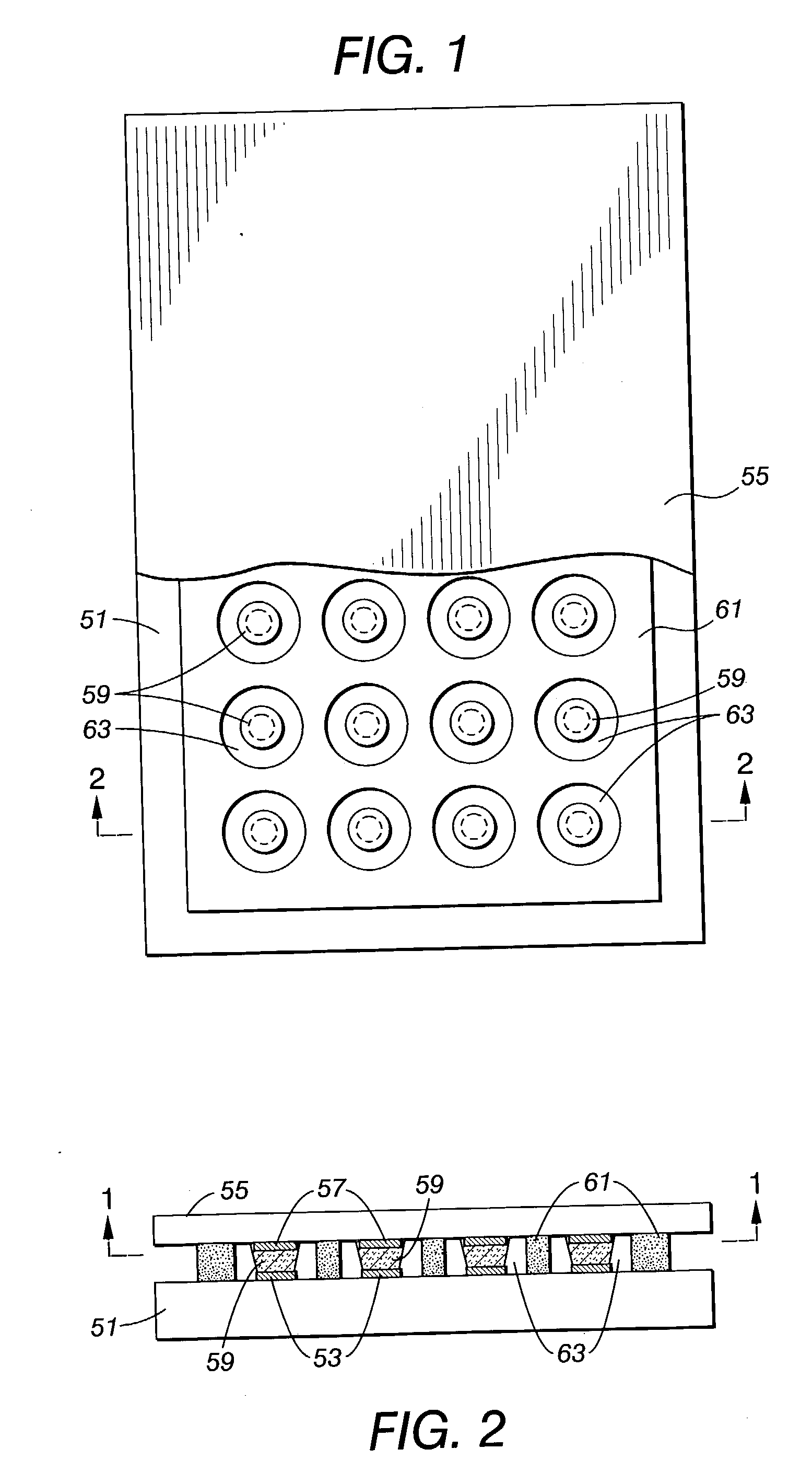
[0006] FIG. 1 and FIG. 2 are a schematic plan view and a schematic elevational cross-sectional view of an embodiment of an interconnected circuit structure that can be made using techniques disclosed herein. The circuit structure includes a first electrical circuit structure 51 that includes a plurality of contact regions 53. The circuit structure further includes a second electrical circuit structure 55 that a plurality of contact regions 57. The contact regions 53 of the first circuit structure 51 are aligned with the contact regions 57 of the second circuit structure 55. The contact regions 53 are electrically interconnected to corresponding contact regions 57 by conductive islands or bumps 59. A patterned standoff structure 61 is disposed between the first circuit structure and the second circuit structure. The standoff structure 61 includes a plurality of apertures 63, each of which surrounds an interconnection of a contact region 53, a conductive bump 59, and a contact region ...
PUM
| Property | Measurement | Unit |
|---|---|---|
| diameter | aaaaa | aaaaa |
| diameter | aaaaa | aaaaa |
| thickness | aaaaa | aaaaa |
Abstract
Description
Claims
Application Information