
Emergency brake device of elevator

Inactive Publication Date: 2004-12-30
MITSUBISHI ELECTRIC CORP
View PDF15 Cites 33 Cited by
  • Summary
  • Abstract
  • Description
  • Claims
  • Application Information

AI Technical Summary

Benefits of technology

[0009] With this invention, it is contemplated as an object thereof to solve the problems mentioned above by providing an emergency brake apparatus for the elevator system which requires especially any additional space for installation in a machine room or the like and which is capable of preventing abrupt movement of the elevator cage in the downward direction or upward direction while protecting the rope from damage with a simplified structure capable of being manufactured inexpensively.

Problems solved by technology

It is conceivable that passengers of an elevator car or cage may suffer injuries if the elevator cage should abruptly move downwardly or upwardly due to accidents or the like which may occur when the passengers are getting on or off the elevator cage or due to a fault of a brake of a hoisting machine, malfunction of an electric control system and others.
However, the conventional emergency brake apparatuses for the elevator system of the structures described above suffer problems that a large space for installing the brake apparatus in the machine room or other is required, that the main rope may undergo damage, that the brake apparatuses are very expensive because of complicated structures, and so forth.
Furthermore, the conventional apparatuses shown in FIGS. 7 and 8 suffer an additional problem that although they are effective for the upward movement at a speed higher than the rated one, it is impossible to prevent occurrence of accident due to unexpected or abrupt movement of the elevator cage in the downward or upward direction from the stationary state.

Method used


Image

  • Emergency brake device of elevator
  • Emergency brake device of elevator
  • Emergency brake device of elevator

Examples


embodiment 1

[0024] Embodiment 1

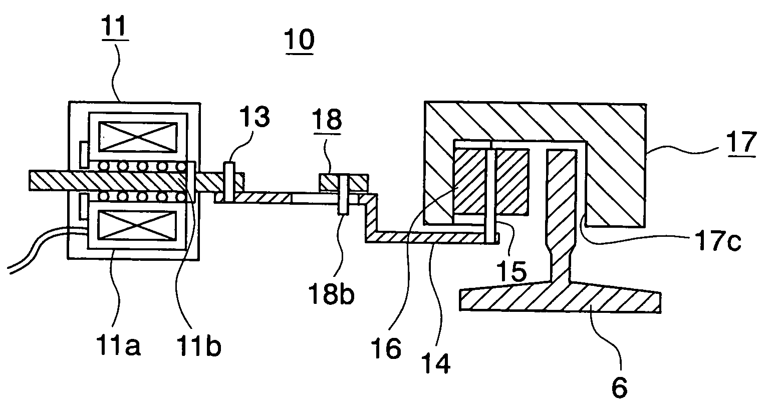
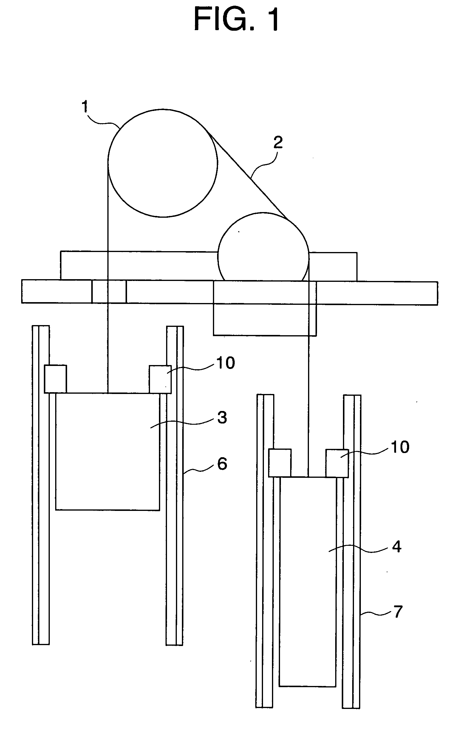
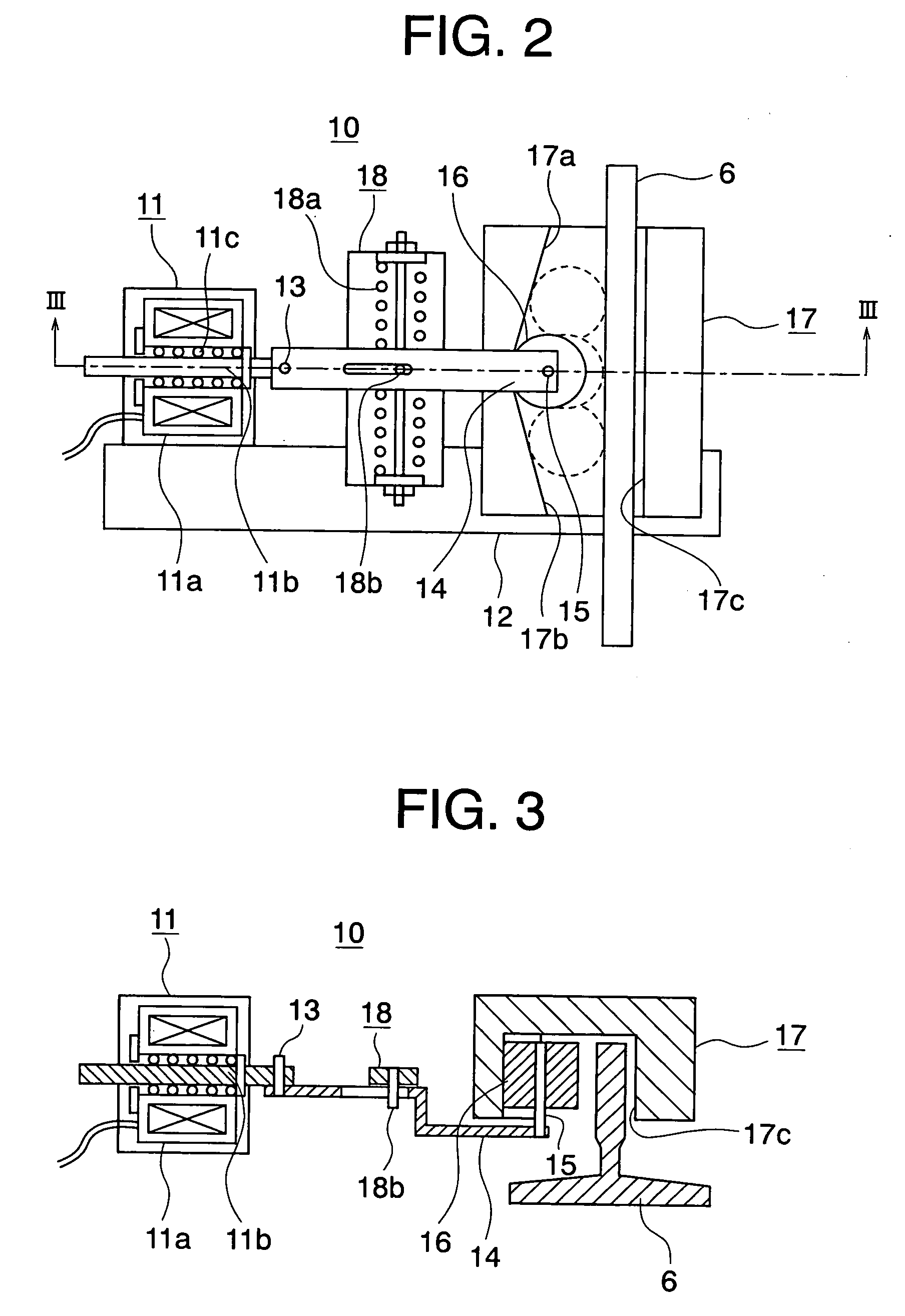
[0025] FIG. 1 is a schematic diagram showing a location at which the emergency brake apparatus according to this invention is installed. FIG. 2 is a front view showing the emergency brake apparatus according to a first embodiment of this invention. Further, FIG. 3 is a sectional view of the same taken along a line III-III shown in FIG. 2 and viewed in the direction indicated by arrows.

[0026] FIG. 1 shows the interior of a machine room and an elevator shaft. A sheave 1 of a hoisting machine installed within the machine room is wound with a main rope 2. An elevator cage 3 and a balance weight 4 are fixedly connected to the main rope 2 at both ends thereof, respectively. The elevator cage 3 is guided by means of cage guide rails 6 internally of the elevator shaft. The balance weight 4 is guided by means of weight guide rails 7. As the sheave 1 of the hoisting machine rotates, the elevator cage 3 moves upwardly or downwardly within the elevator shaft.

[0027] The emerge...

embodiment 2

[0039] Embodiment 2

[0040] FIG. 5 is a front view showing the emergency brake apparatus according to a second embodiment of this invention. Further, FIG. 6 is a sectional view of the same taken along a line VI-VI shown in FIG. 5 and viewed in the direction indicated by arrows.

[0041] In the emergency brake apparatus 21 according to the instant embodiment of the invention, the grip member 19 includes a pressing member 19d disposed oppositely to the paired slant surfaces 19a and 19b. The pressing member 19d is supported by means of springs 19g serving as elastic members from a planar surface 19f. In the emergency brake apparatus according to the instant embodiment, a pressing surface 19c is formed on a side surface of the pressing member 19d and positioned adjacent to the guide rail 6.

[0042] Furthermore, in the emergency brake apparatus according to the instant embodiment of the invention, the pressing member gripped or sandwiched between the grip member 19 and the guide rail 6 is const...


PUM


Abstract

An emergency brake apparatus for an elevator system is installed on an elevator cage or a balance weight of the elevator system and includes a grip member comprised of slant surfaces and a pressing surface disposed so as to sandwich a guide rail therebetween, a pressing member disposed movably between the slant surfaces of the grip member and the guide rail, and an electric solenoid connected to the pressing member and put into operation in response to an electric signal inputted, wherein the electric solenoid is so arranged as to position the pressing member away from the guide rail in an ordinary operation while pushing the pressing member into between the slant surfaces and the guide rail.

Description

[0001] This invention relates to an emergency brake apparatus for an elevator system, and more particularly the invention is concerned with an emergency brake apparatus which is adapted to be installed in combination with an elevator car or cage or a balance weight.BACKGROUND TECHNIQUES[0002] It is conceivable that passengers of an elevator car or cage may suffer injuries if the elevator cage should abruptly move downwardly or upwardly due to accidents or the like which may occur when the passengers are getting on or off the elevator cage or due to a fault of a brake of a hoisting machine, malfunction of an electric control system and others. As the measures for coping with occurrence of such unwanted situations or events, an emergency stopping apparatus or a speed governor has heretofore been installed in association with a balance weight or a rope brake designed for directly gripping a main rope has been installed internally of a machine room. These conventional emergency brake ap...

Claims


Application Information

Patent Timeline
IPC IPC(8): B66B5/22B66B5/24
CPCB66B5/185B66B5/22B66B5/16
Inventor ITO, KAZUMASA
Owner MITSUBISHI ELECTRIC CORP
Features
  • Generate Ideas
  • Intellectual Property
  • Life Sciences
  • Materials
  • Tech Scout
  • Unparalleled Data Quality
  • Higher Quality Content
  • 60% Fewer Hallucinations
Learn More