
Cross-tie

a cross-tie and railway technology, applied in the field of railway tracks, can solve the problems of difficult control of the relative positioning between the running rails, time-consuming and expensive installation of railway tracks, and inability to take into account the effect of the relative positioning of the running rails

Inactive Publication Date: 2005-01-06
BOMBARDIER TRANSPORTATION GMBH
View PDF14 Cites 35 Cited by
  • Summary
  • Abstract
  • Description
  • Claims
  • Application Information

AI Technical Summary

Benefits of technology

[0008] In accordance with another broad aspect, the present invention provides an assembly comprising a cross-tie and at least one stud assembly. The cross tie includes a reaction rail supporting section adapted for supporting a reaction rail, and two running...

Problems solved by technology

A deficiency with this manner of building the railway track is that each one of the rails requires a separate rail fastening arrangement, which makes the railway track time-consuming and expensive to install.
A further deficiency with such traditional railway track is that it is difficult to control the relative positioning between the running rails, the reaction rails and the one or more power rails, which is important for the proper operation of the LIM rail vehicle over the track.
A deficiency with this cross-tie is that it does not take into consideration the relative positioning of the power rail in relation to the running rails and the reaction rails.
In addition, the fact that the running rails and the reaction rails are mounted to the guideway separately from the power rail requires additional fastening studs which results in more work for the person installing the track, and additional parts that can be costly.

Method used


Image

  • Cross-tie
  • Cross-tie
  • Cross-tie

Examples


Embodiment Construction

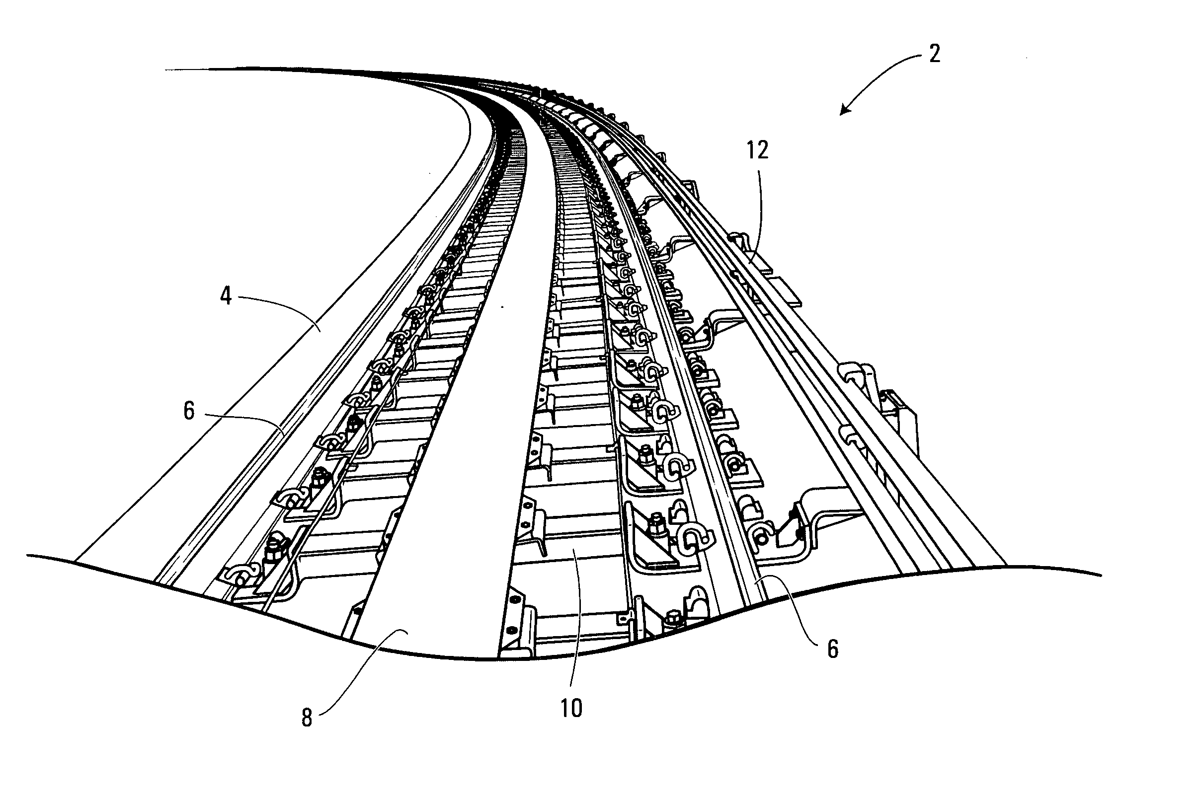
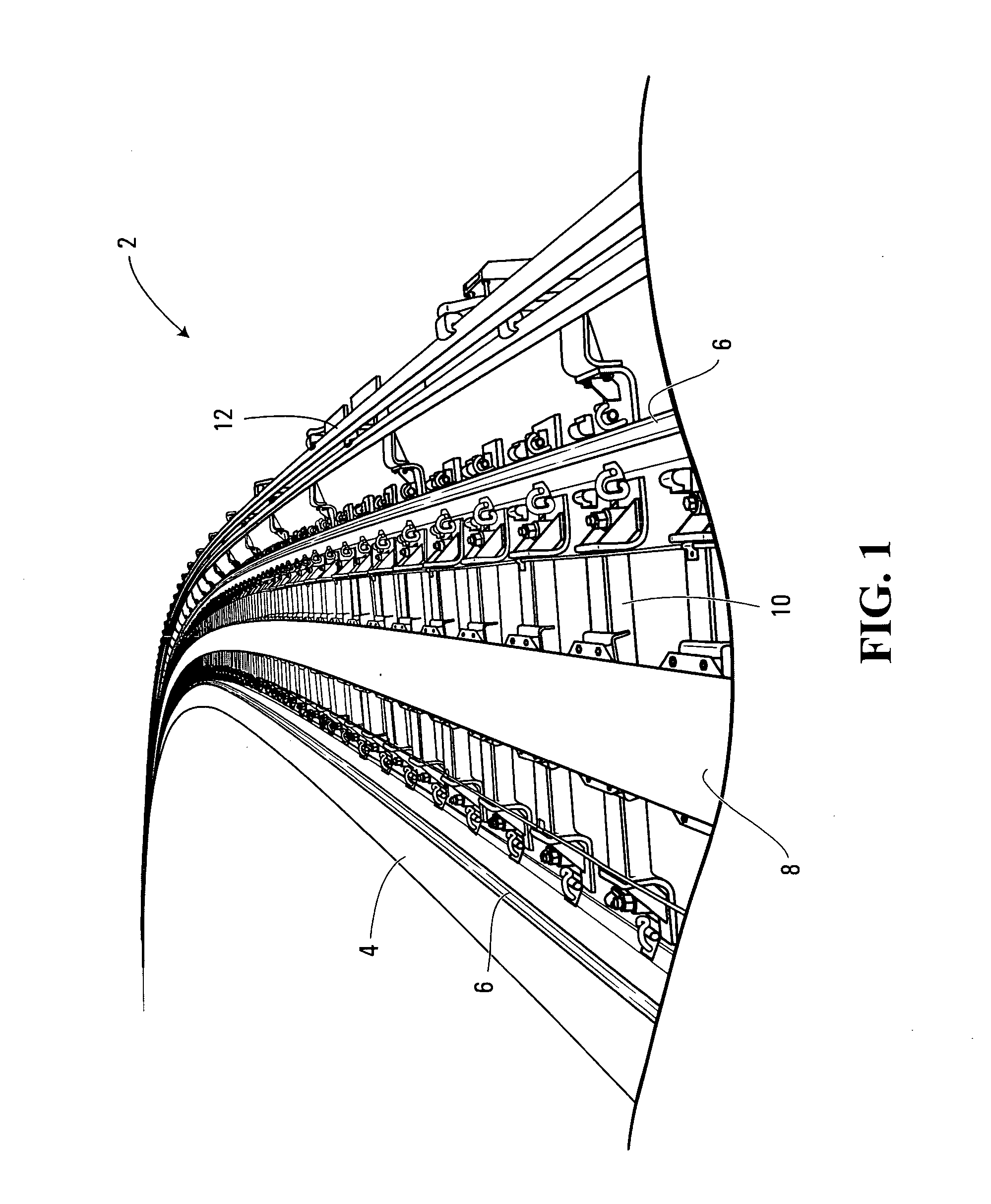
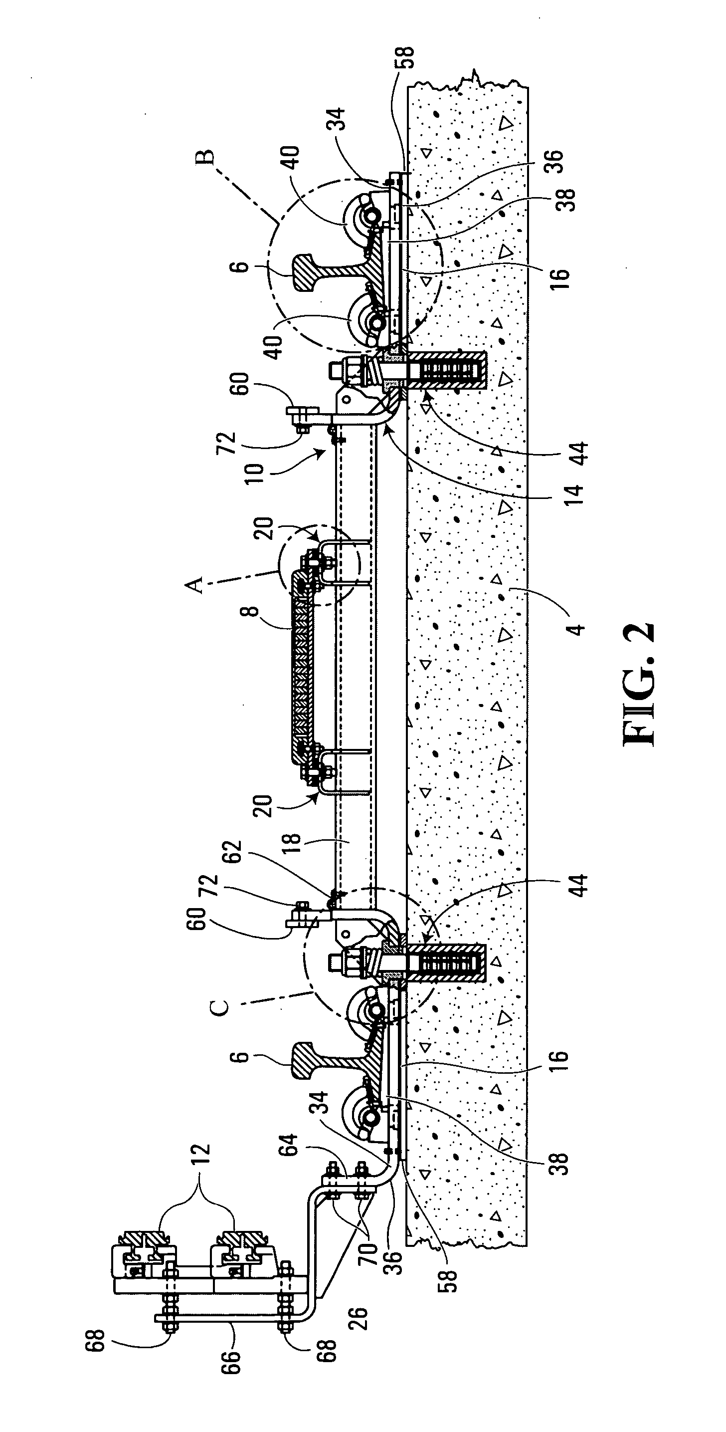
[0020] Shown in FIG. 1 is a railway track 2 for a rail vehicle (not shown) that uses a linear induction motor (LIM) as its primary source of propulsion. The railway track 2 includes a guideway 4 that is typically formed of concrete, and a plurality of cross-ties 10. The cross-ties 10 are operative to support a pair of running rails 6, a reaction rail 8 and at least one power rail 12. In the non-limiting example of implementation shown in FIG. 1, the cross-tie 10 is operative to support two power rails 12.

[0021] As shown, the running rails 6 are positioned on the cross-tie 10 in a parallel, spaced apart relationship, such that the wheels of the railway vehicle can travel therealong. The reaction rail 8 is positioned between the two running rails 6, and is operative to complete a flux path with a primary portion of the linear induction motor located on the railway vehicle, so as to propel or retard the railway vehicle along the track. The power rails 12 are positioned perpendicular t...


PUM


Abstract

The present invention provides a cross-tie having an elongated body that comprises a reaction rail supporting section, two running rail supporting sections and a power rail supporting section. The reaction rail supporting section is adapted for supporting a reaction rail and the two running rail supporting sections are each adapted for supporting a respective running rail. The power rail supporting section is adapted for supporting at least one power rail.

Description

CROSS REFERENCE TO RELATED APPLICATIONS [0001] This application claims priority from provisional U.S. Patent Application Ser. No. 60 / 468,096, which was filed on May 6, 2003.FIELD OF THE INVENTION [0002] The present invention relates generally to the field of railway tracks, and more specifically to cross-ties that are used with railway tracks. BACKGROUND OF THE INVENTION [0003] Railway vehicles that use linear induction motors (LIM) as their primary source of propulsion are known in the art. In general, linear induction motors (LIM) used by railway vehicles consist of a primary portion that is supported under the railway vehicle, and a reaction rail that is supported on the railway track. As such, railway tracks built for LIM railway vehicles include a pair of running rails for supporting the wheels of the railway vehicle, and a reaction rail for interfacing with the primary portion of the linear induction motor. In addition, railway tracks for LIM railway vehicles include at least ...

Claims


Application Information

Patent Timeline
IPC IPC(8): E01B3/00B60M1/30E01B3/16E01B3/32E01B25/00E01B26/00
CPCE01B3/32E01B26/005E01B25/00A45D29/12
Inventor SKOBLENICK, HARRYSTEGLICH, BERNARD
Owner BOMBARDIER TRANSPORTATION GMBH
Learn More