Cam-bolt assembly

a technology of cam-bolt and bolt body, which is applied in the direction of screws, threaded fasteners, transportation and packaging, etc., can solve the problems of reducing the strength of the bolt, affecting the stability of the bolt, and subjecting the bolt to torsional loading

Active Publication Date: 2005-01-06
NEWFREY
View PDF20 Cites 26 Cited by
  • Summary
  • Abstract
  • Description
  • Claims
  • Application Information

AI Technical Summary

Problems solved by technology

Often, the plates are subject to torsional loading, which imparts torsional loading to the bolt.
The notched bolt, becaus

Method used


Image

  • Cam-bolt assembly
  • Cam-bolt assembly
  • Cam-bolt assembly

Examples


Embodiment Construction

[0026] The following description of the preferred embodiments is merely exemplary in nature and is in no way intended to limit the invention, its application, or uses.

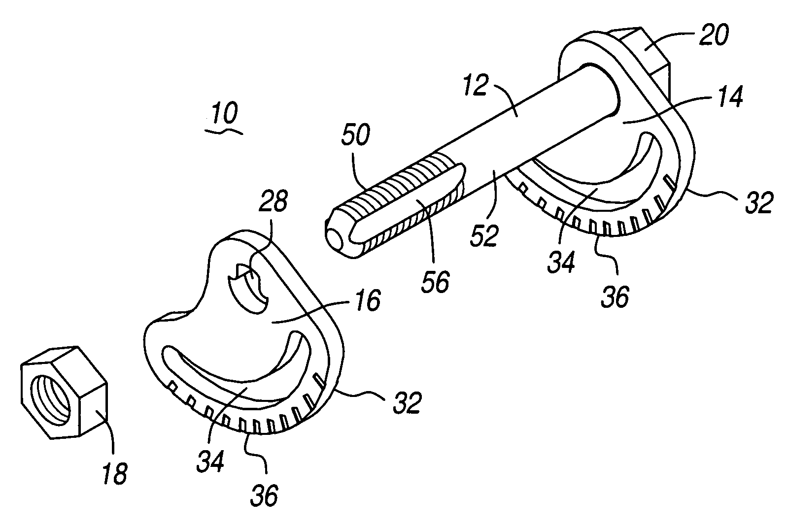
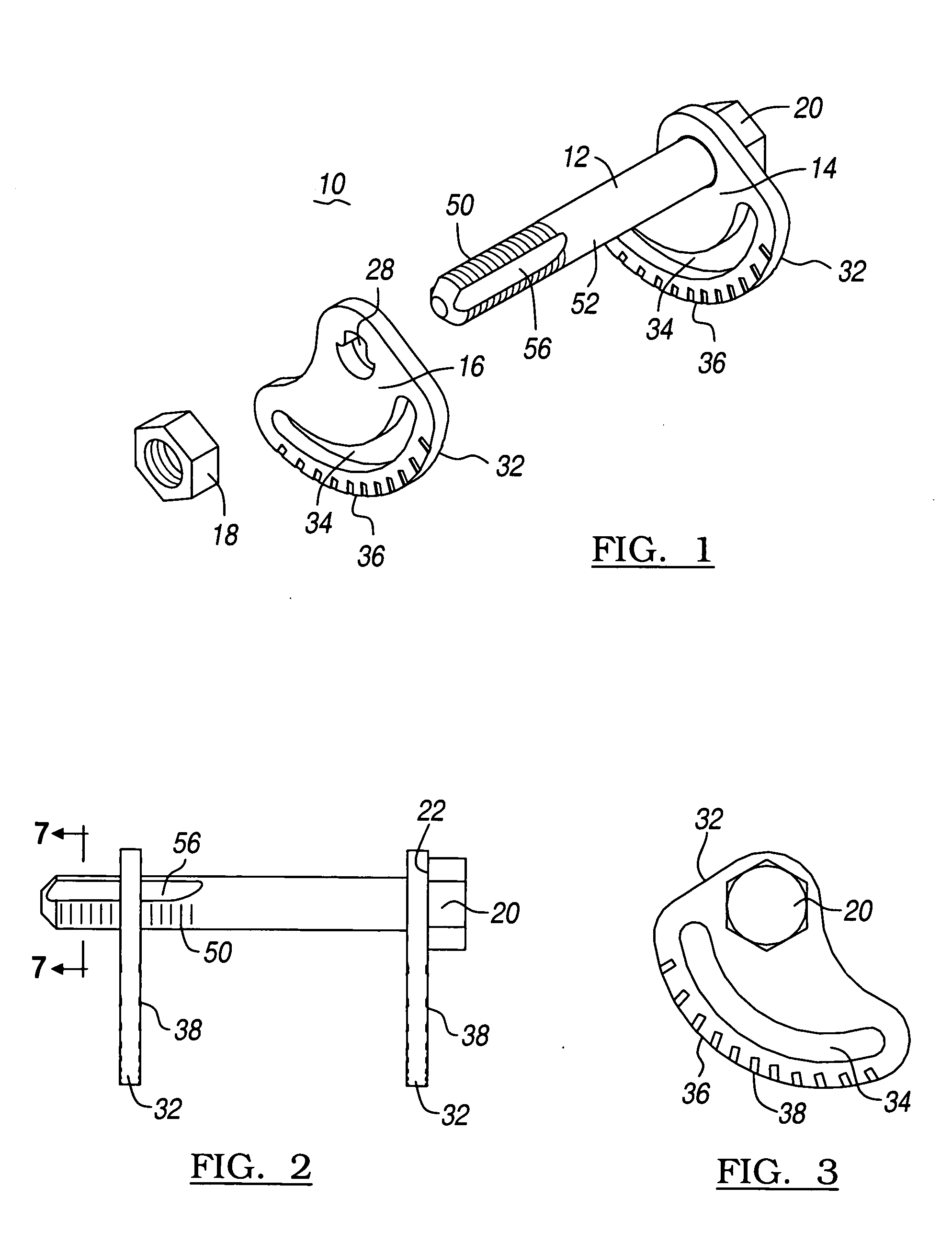
[0027]FIGS. 1 and 2 represent a perspective exploded view and a side view of a cam bolt assembly 10 according to the teachings of the present invention. The cam bolt assembly 10, which is formed of a threaded bolt 12, first cam plate 14, second cam plate 16, and a nut 18, is used in a vehicle's suspension system to adjust the vehicle's wheel alignment. When assembled, the cam bolt assembly is configured to have a rotational tolerance of ±3 degrees.

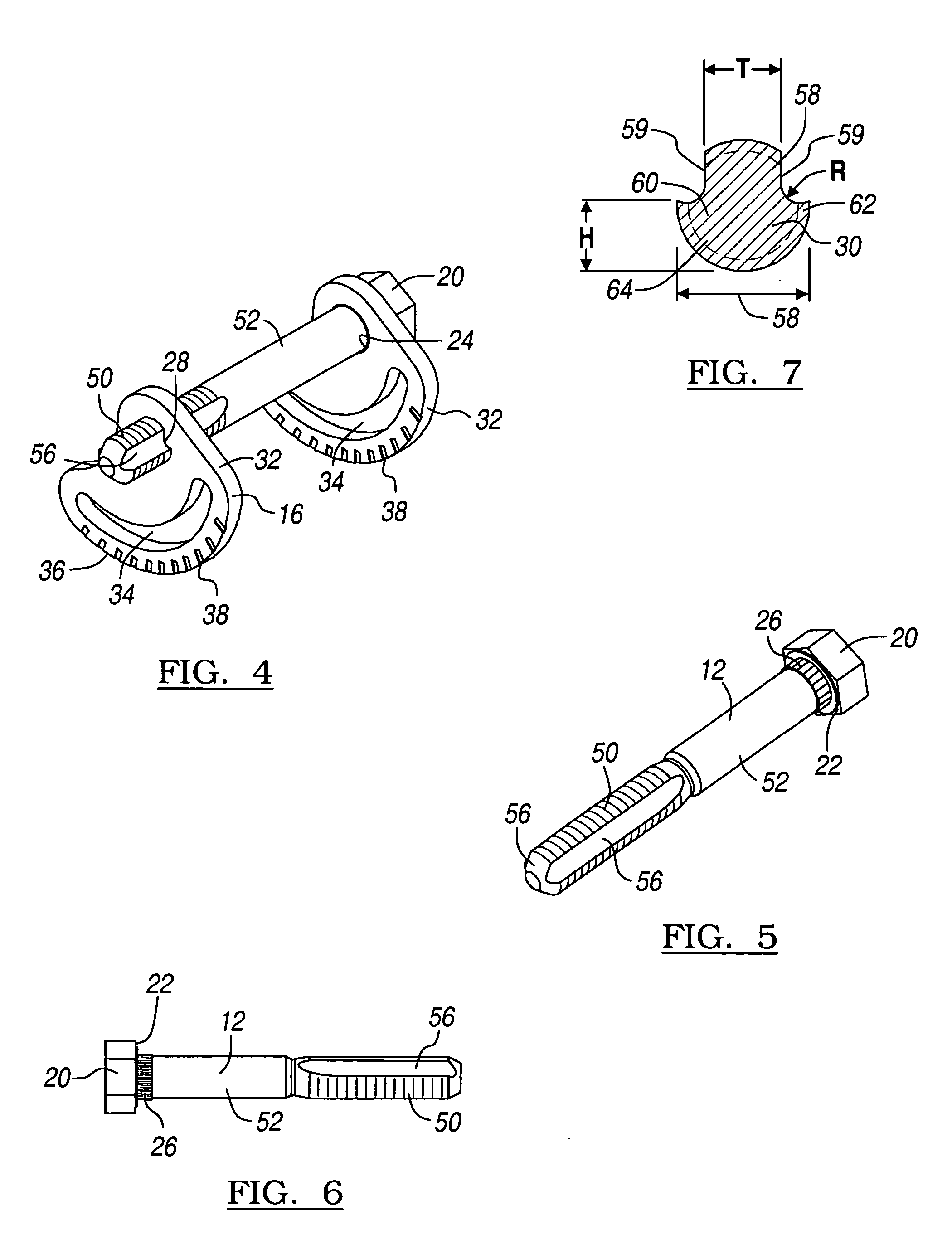
[0028] The threaded bolt 12 has a bolt head 20 having a bolt head inner surface 22 which supports the first cam plate 14. The first cam plate 14 defines a circular aperture 24, which has a radius substantially equal to the diameter of the threaded bolt 12. The first cam plate 14 is rotationally coupled to the threaded bolt 12 by a knurl 26 formed on the threaded bolt 12 adj...


PUM


Abstract

A cam bolt assembly for using in a vehicle's suspension system to adjust the vehicle's wheel alignment is disclosed having a threaded fastener defining a pair of longitudinal channels, a first cam plate is coupled to the threaded bolt, a second cam plate defining an aperture is mated to the pair of longitudinal channels. At least one of the cam plates has an arcuate slot configured to mate with a component of the suspension system.

Description

CROSS-REFERENCE TO RELATED APPLICATIONS [0001] This application is a continuation-in-part of U.S. patent application Ser. No. 10 / 698,134 filed on Oct. 31, 2003, which claims priority to U.S. Provisional Patent Application No. 60 / 423,117 filed on Nov. 1, 2002, both of which are incorporated herein by reference.FIELD OF THE INVENTION [0002] The present invention relates to a cam bolt for a vehicle suspension and, more particularly, to a cam bolt having a locking feature which efficiently couples a cam plate to a bolt without significantly reducing the bolt's effective strength. BACKGROUND OF THE INVENTION [0003] It has been known that plates can be coupled to shafts utilizing a single notch cut into the bolt surface. Traditionally, the plate has a D-shaped hole with a cross-section which corresponds to the cross-section of the notch disposed in the bolt is placed over the bolt and held using a threaded fastener. [0004] Often, the plates are subject to torsional loading, which imparts ...

Claims


Application Information

Patent Timeline
IPC IPC(8): B60G7/02F16B35/04
CPCB60G7/02B60G2200/46F16B35/041B60G2204/422B60G2204/42
Inventor GENICK, RAYMOND M. II
Owner NEWFREY
Why Eureka
Try Eureka