Motor

Inactive Publication Date: 2005-01-06
NIDEC CORP
View PDF7 Cites 16 Cited by
  • Summary
  • Abstract
  • Description
  • Claims
  • Application Information

AI Technical Summary

Benefits of technology

[0012] In addition, when the area of the lower end face of the peripheral wall portion is made small, a retaining for

Problems solved by technology

In addition, when the area of the lower end face of the peripheral wall portion is made small, a retaining force o

Method used


Image

  • Motor
  • Motor
  • Motor

Examples


Embodiment Construction

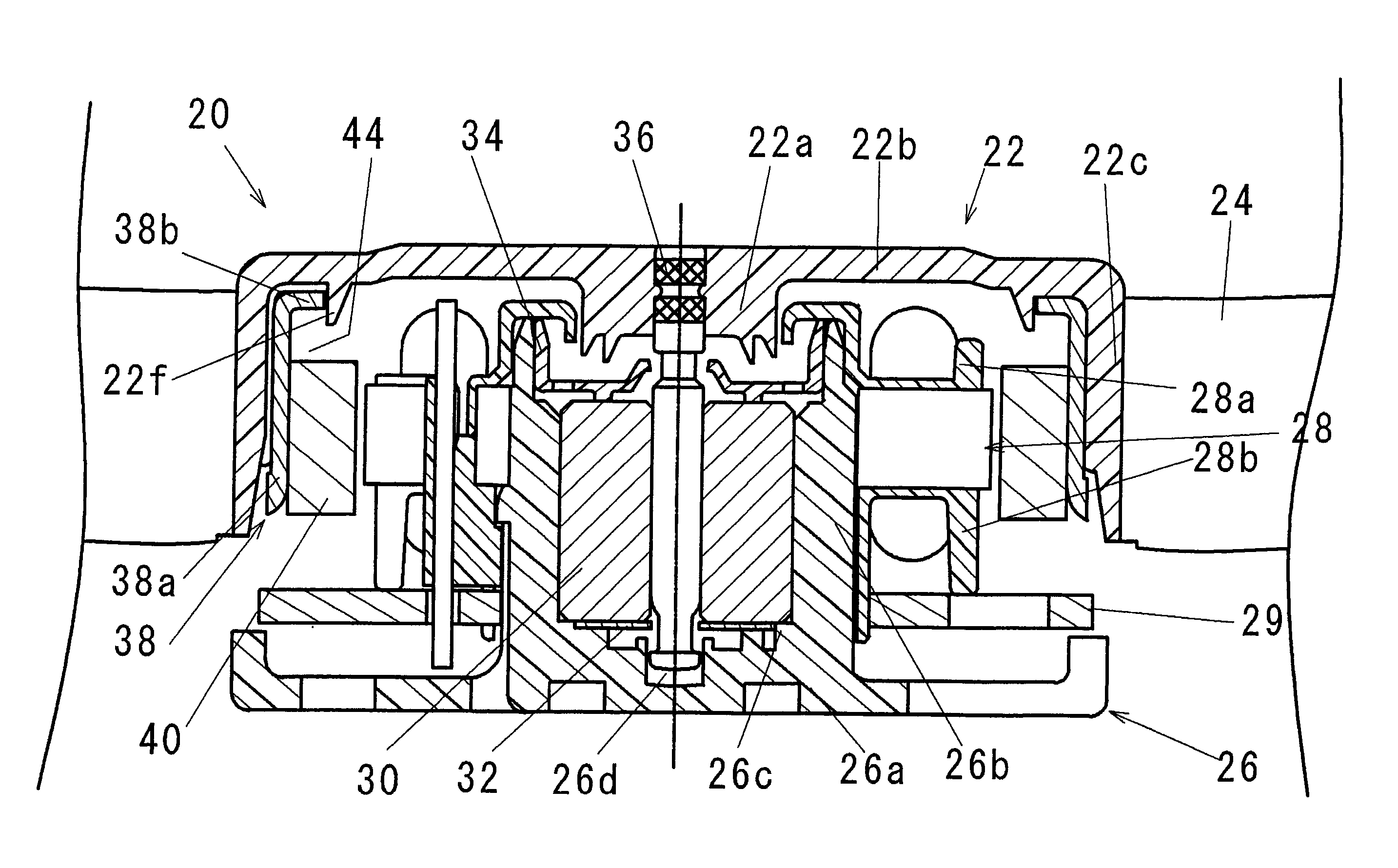
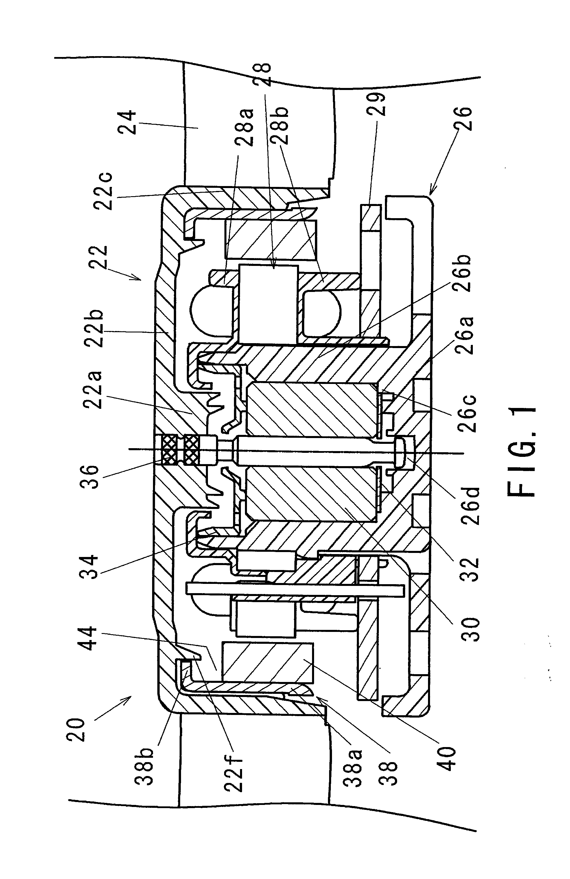
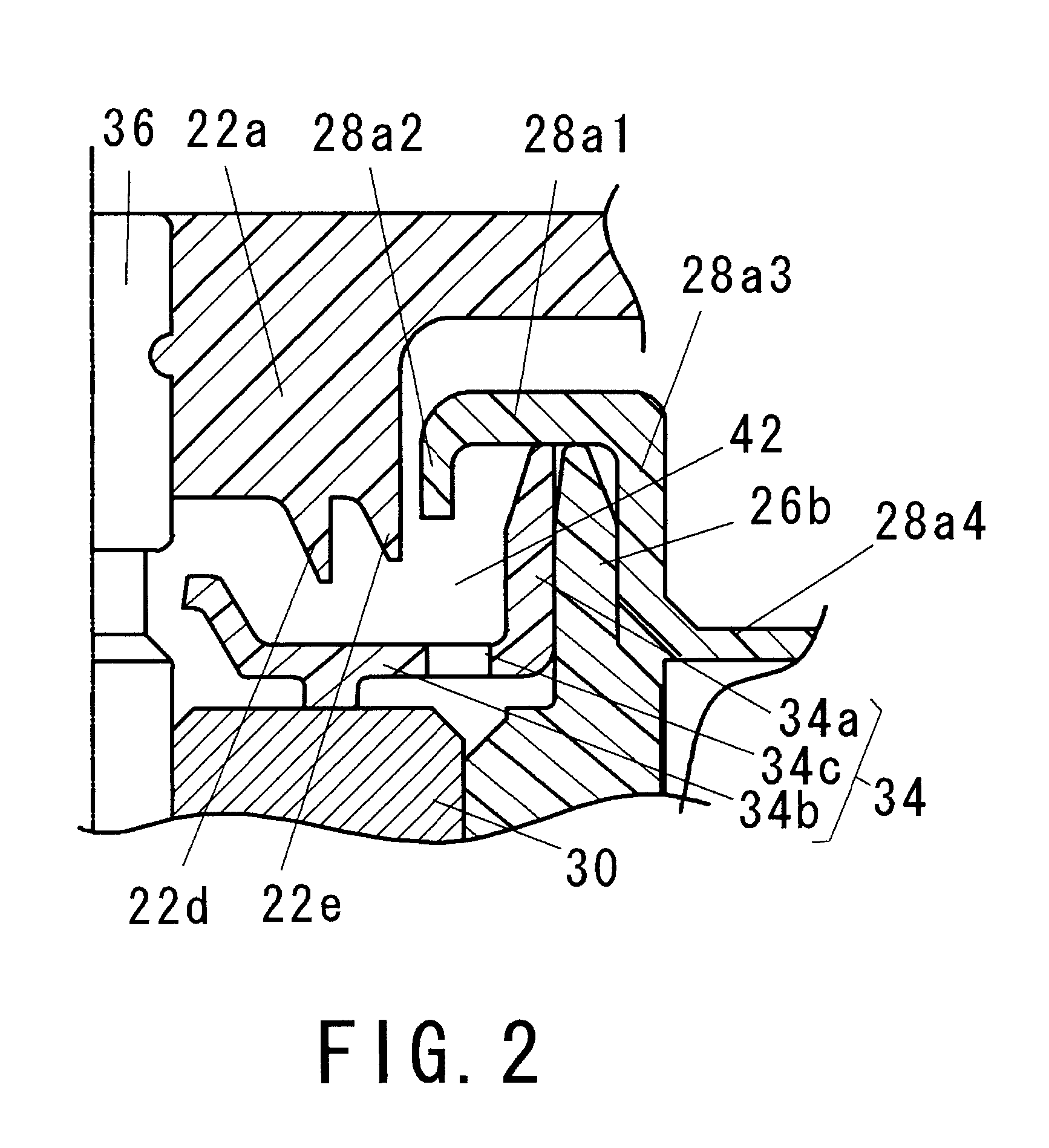
[0024] One embodiment of the present invention will be explained with reference to FIGS. 1 to 3.

[0025] A motor 20 shown in FIG. 1 is a cooling fan motor where a rotor 22 is provided with an impeller 24. The motor 20 is provided with a housing 26 integrally made of synthetic resin and comprising a disc-shaped base portion 26a and a cylindrical bearing holding portion 26b with a bottom provided at a central portion of the base portion 26a. A stator 28 constituted by winding a winding coil on an iron core covered with a pair of insulators 28a and 28b for electrically insulating the iron core and the winding coil is fitted and fixed to an outer peripheral face of the bearing holding portion 26b. The winding coil is electrically connected to a circuit board 29 arranged below the stator 28.

[0026] A cylindrical sleeve 30 where porous metal has been impregnated with lubrication oil is fitted and fixed inside the bearing holding portion 26b by press-fit operation. A lower end face of the s...


PUM


Abstract

A motor of this invention is provided with a sleeve-type bearing impregnated with oil for supporting a rotor assembly including a shaft and a rotor member. A lower face of the rotor is provided with at least two peripheral wall portions, an inner peripheral wall portion and an outer peripheral wall portion, which surround the shaft with a gap therebetween in a radial direction. The peripheral wall portions are accommodated in an annular recessed portion so as to surround an open space over a sleeve constituted the sleeve-type bearing and has a lower top of the most inner part. The lower end of the inner peripheral wall portion is located lower than the lower end of the outer peripheral wall portion, and the lower end of the outer peripheral wall portion is located lower than the lower top of the annular recessed portion.

Description

CROSS REFERENCE TO RELATED APPLICATIONS [0001] The disclosure of Japanese Patent Application No. 2003-190328 filed Jul. 2, 2003 including specification, drawings and claims is incorporated herein by reference in its entirety. BACKGROUND OF INVENTION [0002] 1. Field of the Invention [0003] The present invention relates to a motor in which a sleeve-type bearing impregnated with oil is used. [0004] 2. Description of the Related Art [0005] As shown in FIG. 10, a conventional motor in which a sleeve-type bearing is used is constituted such that a sleeve2 impregnated with oil is fitted and fixed inside a cylindrical portion la of a housing 1 with a bottom and a shaft 3 is rotatably supported by the sleeve 2. The sleeve 2 is provided as a porous body made of a sintered metal impregnated with oil. A stator 4 is fitted and fixed to an outer peripheral face of the cylindrical portion 1a. A rotor 5 made of synthetic resin and injection-molded is integrally fixed to an upper end of the shaft 3....

Claims


Application Information

Patent Timeline
IPC IPC(8): F16C33/10F16C33/74F16C35/02H02K5/10H02K5/167H02K7/08H02K7/14
CPCF16C33/103H02K5/1675F16C33/74
Inventor TAKAHASHI, SHUJIMURATA, SHINICHIINOUE, TOMOYUKI
Owner NIDEC CORP
Why Eureka
Try Eureka