Multi-test circuit interrupter locator and circuit interrupter tester

a multi-test circuit and locator technology, applied in the direction of line-transmission monitoring/testing, line-transmission details, instruments, etc., can solve the problems of significant fires, time-consuming methods, and inability to test circuits,

Inactive Publication Date: 2005-01-06
UNIQUE TECH
View PDF14 Cites 47 Cited by
  • Summary
  • Abstract
  • Description
  • Claims
  • Application Information

AI Technical Summary

Benefits of technology

Some of the foregoing needs are met and problems solved by a multi-function testing system. In accordance with systems consistent with the present invention, a testing system is provided that includes a hand-held transmitter that plugs into a receptacle electrically coupled to a selected branch circuit. The transmitter has a circuit effective to test an arc fault circuit interrupter electrically coupled to the selected branch circuit by creating a pulse on the branch circuit that is effective to trip the arc fault circuit interrupter. The transmitter can perform a test of determining whether the receptacle is wired properly.

Problems solved by technology

Manual identification of the fuse or circuit breaker can be accomplished by removing each fuse or opening each circuit breaker, thereby disrupting the power flow through the circuit.
This method is not only time consuming, but also may not be feasible in situations where it would be hazardous to interrupt the power flow to certain branch circuit outlets, i.e., in a hospital or in environments where there are computers in use without backup power.
A significant number of fires are caused not by sustained short circuits, but by arc faults.
Although the arc fault may not draw enough continuous current to trip a conventional electromagnetic circuit interrupter, it can still cause enough localized heat to ignite surrounding flammable substances and cause a fire.
However, to conduct such a test the user must go to the circuit breaker panel, which is often in an inconvenient location.
Further, without additional equipment, it is typically not easy to determine that a given receptacle in a bedroom is actually connected to the circuit that is protected by the AFCI.

Method used


Image

  • Multi-test circuit interrupter locator and circuit interrupter tester
  • Multi-test circuit interrupter locator and circuit interrupter tester
  • Multi-test circuit interrupter locator and circuit interrupter tester

Examples


Embodiment Construction

While the present invention may be embodied in many different forms, there are shown in the drawings and discussed herein several potential embodiments with the understanding that the present disclosure is to be considered only as an exemplification of the principles of the invention and is not intended to limit the invention to the embodiments illustrated.

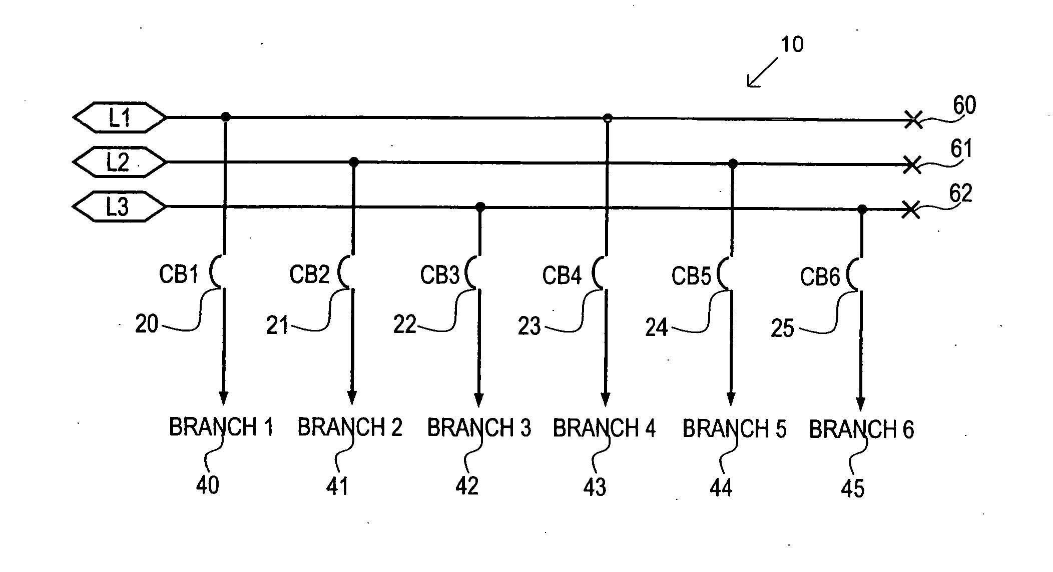
The present system as disclosed herein can perform a number of tests. Specifically, the system locates the circuit interrupter associated with a particular branch circuit from amongst a plurality of circuit interrupting devices, checks receptacle wiring, and tests the circuit interrupter. FIG. 1 schematically depicts a potential AC power distribution panel 10 having three power line bus bars 60, 61 and 62 and a plurality of circuit interrupting devices (CB1, CB2, CB3, CB4, CB5 and CB6) each connected in series between a respective bus bar and a respective branch circuit (40, 41, 42, 43, 44, and 45, respectively). Although AC po...


PUM


Abstract

A testing system includes a hand-held transmitter that plugs into a receptacle electrically coupled to a selected branch circuit. The transmitter includes a circuit effective to test an arc fault circuit interrupter electrically coupled to the branch circuit by creating a first pulse on the branch circuit that is effective to trip the arc fault circuit interrupter. The transmitter can perform at least one additional test including: determining whether the receptacle is wired properly; determining a location of a circuit interrupting device electrically coupled to the branch circuit by creating a second pulse on the branch circuit that can be sensed by a receiver located proximately to the respective circuit interrupting device and broadly tuned about a frequency of the second pulse; and testing a ground fault circuit interrupter electrically coupled to the branch circuit by creating a third pulse on the branch circuit that is effective to trip the ground fault circuit interrupter.

Description

FIELD OF THE INVENTION The present invention relates in general to devices for testing electrical components and, in particular, to a system for distinguishing the circuit-interrupting device (circuit breaker or fuse) associated with a particular electrical line from a plurality of circuit interrupting devices and for testing arc fault and ground fault circuit interrupters. 1. Background Art When electrical work needs to be performed on an electrical system in a building or facility, it is typically necessary to trace and identify which circuit interrupter device (i.e., circuit breaker or fuse) is supplying power to a specific AC power branch circuit. Manual identification of the fuse or circuit breaker can be accomplished by removing each fuse or opening each circuit breaker, thereby disrupting the power flow through the circuit. Each test point must subsequently be examined to determine whether the power to the test point has been disconnected. This method is not only time con...

Claims


Application Information

Patent Timeline
Patent Type & Authority Applications(United States)
IPC IPC(8): G01R19/00
CPCG01R31/3277G01R31/041G01R31/67
Inventor BERLAND, KERRYBUDNIAK, MITCHELLBERLAND, PAULCOIA, RONALD A.MCGANN, THOMAS
Owner UNIQUE TECH
Why Eureka
Try Eureka