Method for multiple-phase splitting by phase interpolation and circuit the same

US20050001665A1Active Publication Date: 2005-01-06VIA TECH INC

Image

  • Method for multiple-phase splitting by phase interpolation and circuit the same
  • Method for multiple-phase splitting by phase interpolation and circuit the same
  • Method for multiple-phase splitting by phase interpolation and circuit the same

Examples


Embodiment Construction

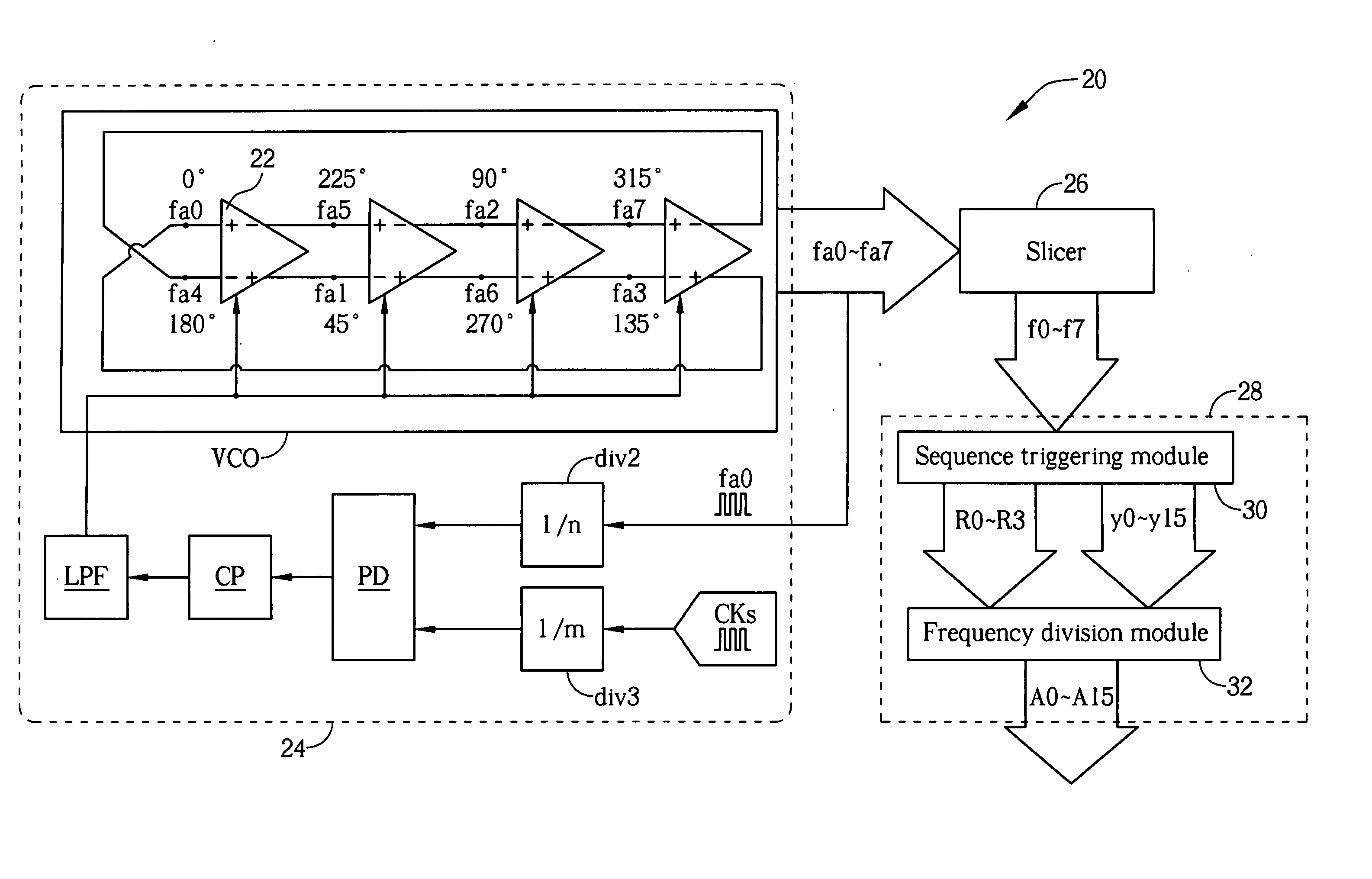
[0025] Please refer to FIG. 5 showing a block diagram of a multiple-phase generating circuit 20 according to the present invention. The multiple-phase generating circuit 20 includes a clock generator 24, a slicer (waveform reshaper) 26, and a phase interpolator 28. When generating a plurality of output clocks of a specific frequency but different phases, the clock generator 24 generates reference clocks of the same frequency but different phases whose frequency is double the frequency of the output clocks. After waveform shaping by the slicer 26, the reference clocks will be input into the phase interpolator 28 to generate a plurality of output clocks of the same frequency but different phases.

[0026] Assuming that the multiple-phase generating circuit 20 generates 16 clocks A0-A15 of the same frequency but different phases, the clock generator 24 generates 8 reference clocks fa0-fa7 of the same frequency but different phases whose frequency is twice the frequency of the output cloc...


PUM


Abstract

The invention relates to a method and related circuitry for multiple phase-splitting. The method includes: while generating M output clocks with a same frequency f1 and different phases, generating N reference clocks with a same frequency (M / N)*f1 and different phases (wherein M>N), and triggering (N / M) frequency division using different periods within each reference clock to generate (M / N) output clocks of different phases for each reference clock, such that the M output clocks of different phases are generated from the N reference clocks of different phases.

Description

BACKGROUND OF INVENTION [0001] 1. Field of the Invention [0002] The present invention relates to a method and a related circuit for phase splitting, and more specifically, to a method and a related circuit for phase splitting by phase interpolation according to multi-phase reference clocks. [0003] 2. Description of the Prior Art [0004] In the modern information-oriented society, electronic apparatuses for processing and storing digital information require higher operating speeds and higher circuit densities. Accordingly, the precision of circuit control and operation becomes important. For instance, the timing control of a CD-ROM drive requires precise management. Although a CD-ROM drive can analyze light reflected from a CD to find a clock for synchronous time control, it requires a clock period to be divided into a plurality of different time points in order to control data write / access precisely. In addition, devices such as a time-to-digital converter (TDC) or a time delay calib...

Claims


Application Information

Patent Timeline
06 Jan 2005
Publication
US20050001665A1
IPC
G11B20/10; H03B27/00; H03K3/03; H03K3/26; H03K5/00; H03K5/08; H03K5/13; H03K5/15; H03K23/68; H03L7/099; H03L7/18
CPC
H03K3/0322; H03K5/08; H03K5/133; H03L7/18; H03K23/68; H03K2005/00286; H03L7/0998; H03K5/1506
Inventors
LIN, ROGER