Condensing unit configuration system

Active Publication Date: 2005-01-06
EMERSON CLIMATE TECH INC
View PDF3 Cites 7 Cited by
  • Summary
  • Abstract
  • Description
  • Claims
  • Application Information

AI Technical Summary

Benefits of technology

[0014] In another feature, the method further comprises determining high and low side options such as low ambient controls, pressure vessel (receiver) and shut-off valves.
[0015] In yet another feature, the method fur

Problems solved by technology

As a result, repetitive design and testing steps are typically require

Method used


Image

  • Condensing unit configuration system
  • Condensing unit configuration system
  • Condensing unit configuration system

Examples


Embodiment Construction

[0045] The following description of the preferred embodiments is merely exemplary in nature and is in no way intended to limit the invention, its application, or uses.

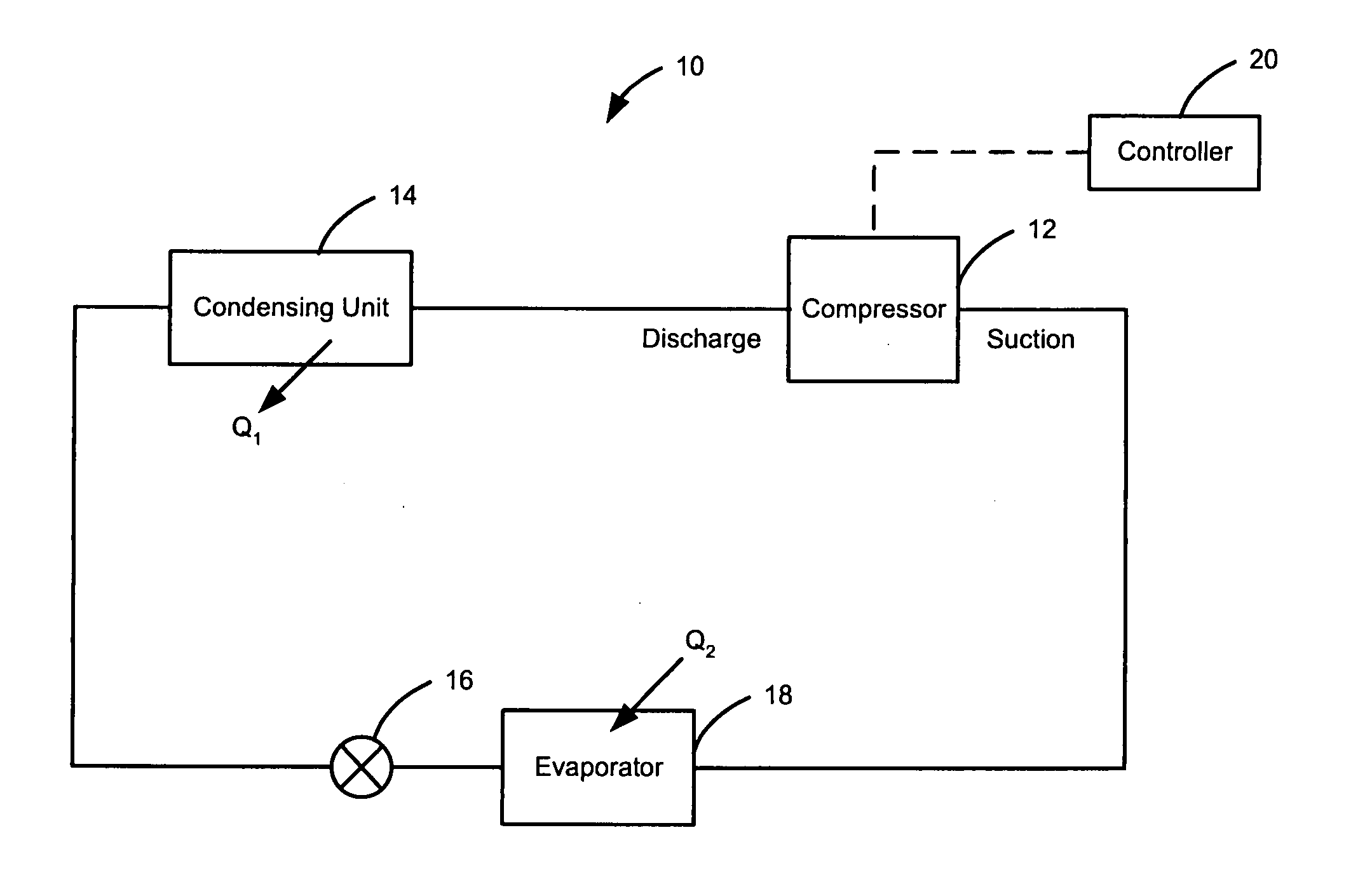
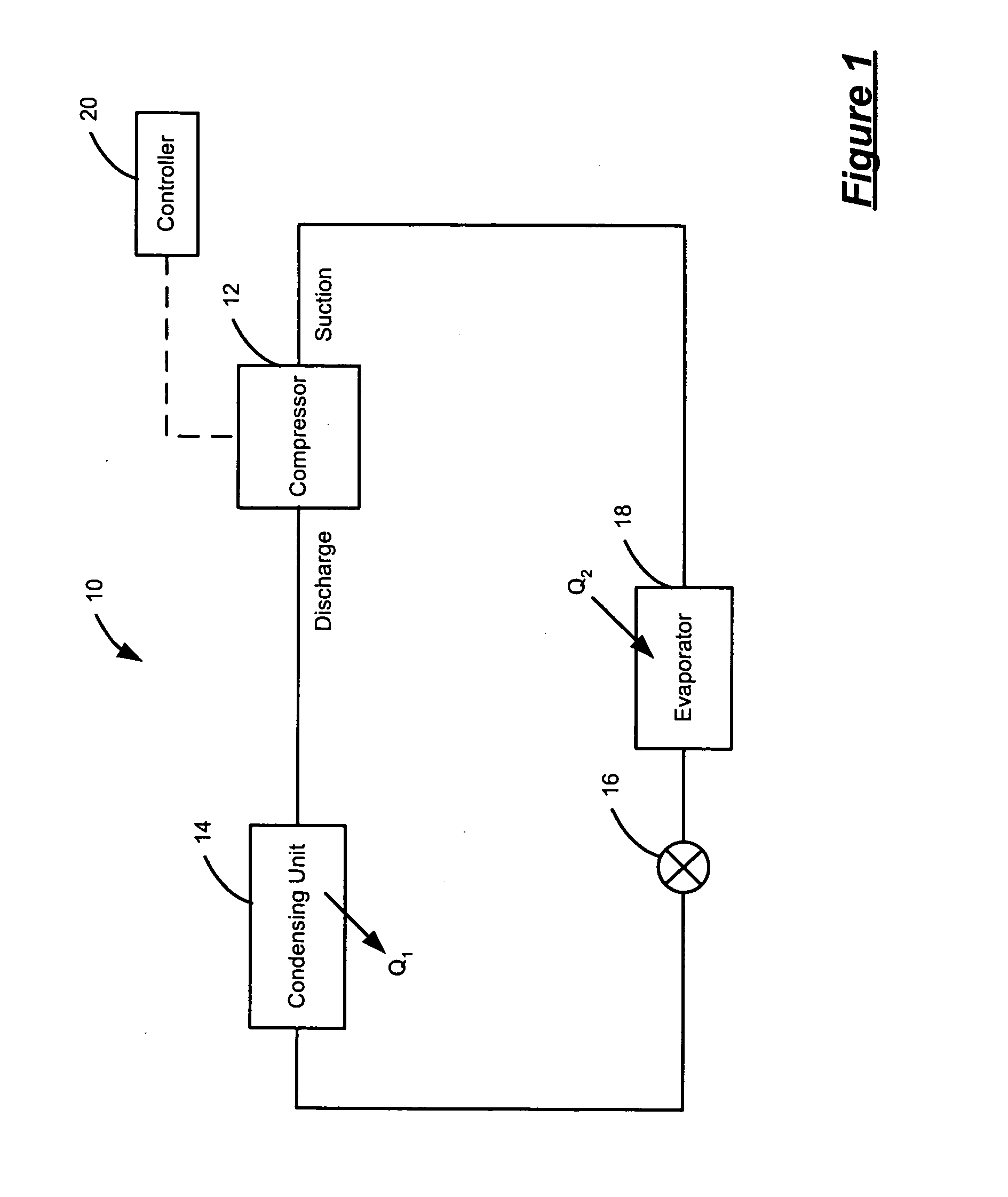
[0046] Referring now to FIG. 1, a generic cooling system 10 includes a compressor 12, a condensing unit 14, an expansion valve 16 and an evaporator 18. The compressor 12 is controlled by a controller 20 and compresses gaseous refrigerant exiting the evaporator 18. The compressor 12 discharges the high pressure refrigerant to the condensing unit 14. The condensing unit 14 operates as a heat exchanger enabling heat transfer (Q1) from the gaseous refrigerant to a heat sink (e.g., air or water). The refrigerant condenses within the condensing unit 14 and a state change occurs from gas to liquid. The liquid refrigerant exits the condensing unit 14 and flows to the evaporator 18 through the expansion valve 16. The evaporator 18 also operates as a heat exchanger enabling heat transfer (Q2) from the atmosphere surrounding the...


PUM


Abstract

A system and method for configuring a condensing unit for a cooling system includes inputting one of a cooling system characteristic, a condensing unit characteristic and a compressor characteristic for the cooling system, applying embedded design rules and accessing a condensing unit database of component attributes and their relationships. A base condensing unit is determined based on the one of a cooling system characteristic, a condensing unit characteristic and a compressor characteristic for the cooling system. The method further includes selecting various accessories of the condensing unit for customizing the base condensing unit based on the particular application.

Description

CROSS-REFERENCE TO RELATED APPLICATIONS [0001] This application claims the benefit of U.S. Provisional Application No. 60 / 477,562, filed on Jun. 11, 2003.FIELD OF THE INVENTION [0002] The present invention relates to condensers, and more particularly to configuring a condensing unit for an air-conditioning or refrigeration system. BACKGROUND OF THE INVENTION [0003] Traditional cooling systems, such as refrigeration and air-conditioning systems, include a compressor, a condensing unit, an expansion valve and an evaporator. The compressor compresses gaseous refrigerant exiting the evaporator and discharges the high pressure refrigerant to the condensing unit. The condensing unit operates as a heat exchanger enabling heat transfer from the gaseous refrigerant to a heat sink (e.g. air or water). The refrigerant condenses within the condensing unit and a state change occurs from gas to liquid. The liquid refrigerant exits the condensing unit and flows to the evaporator through the expans...

Claims


Application Information

Patent Timeline
IPC IPC(8): F25B1/00G06F19/00
CPCF25B2500/05F25B1/00
Inventor BAHEL, VIJAYCRONE, THOMAS E.MONNIN, DEBORAH L.HOSSAIN, ALTAF
Owner EMERSON CLIMATE TECH INC
Why Eureka
Try Eureka