
Hybrid router

a router and hybrid technology, applied in the field of hybrid routers, can solve the problems of more difficult installation and operation of the router table, and achieve the effect of facilitating and common feeling of operation

Active Publication Date: 2005-01-13
CREDO TECH CORP
View PDF33 Cites 38 Cited by
  • Summary
  • Abstract
  • Description
  • Claims
  • Application Information

AI Technical Summary

Benefits of technology

[0005] The present invention is directed to a hybrid router that is capable of operating as a fixed or a plunge router wherein the preferred embodiment thereof comprises a motor assembly that has a housing containing a motor as well as operating handles attached to the housing and operating controls for operating the motor, with the motor assembly can be removably installed in either a fixed base assembly or a plunge base assembly. The preferred embodiment has a rotatable adjustment knob that is located on the motor assembly that can engage the depth adjustment mechanism of either of the fixed or plunge base assemblies. The plunge base assembly has a plunge lock lever that is conveniently located adjacent one of the handles of the motor assembly which contributes to the convenience and common feel of operation regardless of which base assembly is being used with the motor assembly.
[0007] Another aspect of the preferred embodiment of the present invention lies in the depth control mechanism of the plunge base assembly for establishing a desired depth of cut during a plunge operation, where the depth control mechanism is adapted to easily and conveniently establish a zero position when the tip of the router bit touches the surface upon which the router is resting and to thereafter easily and accurately determine a depth of cut.

Problems solved by technology

Some users greatly prefer using a plunge router for freehand use even though they believe that it is more difficult to install and operate in a router table.

Method used


Image

  • Hybrid router
  • Hybrid router
  • Hybrid router

Examples


Embodiment Construction

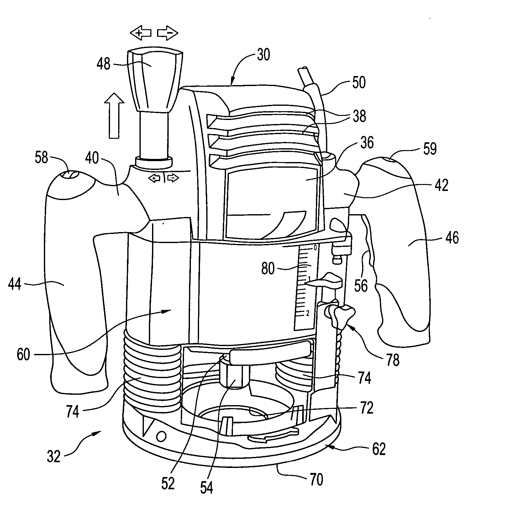
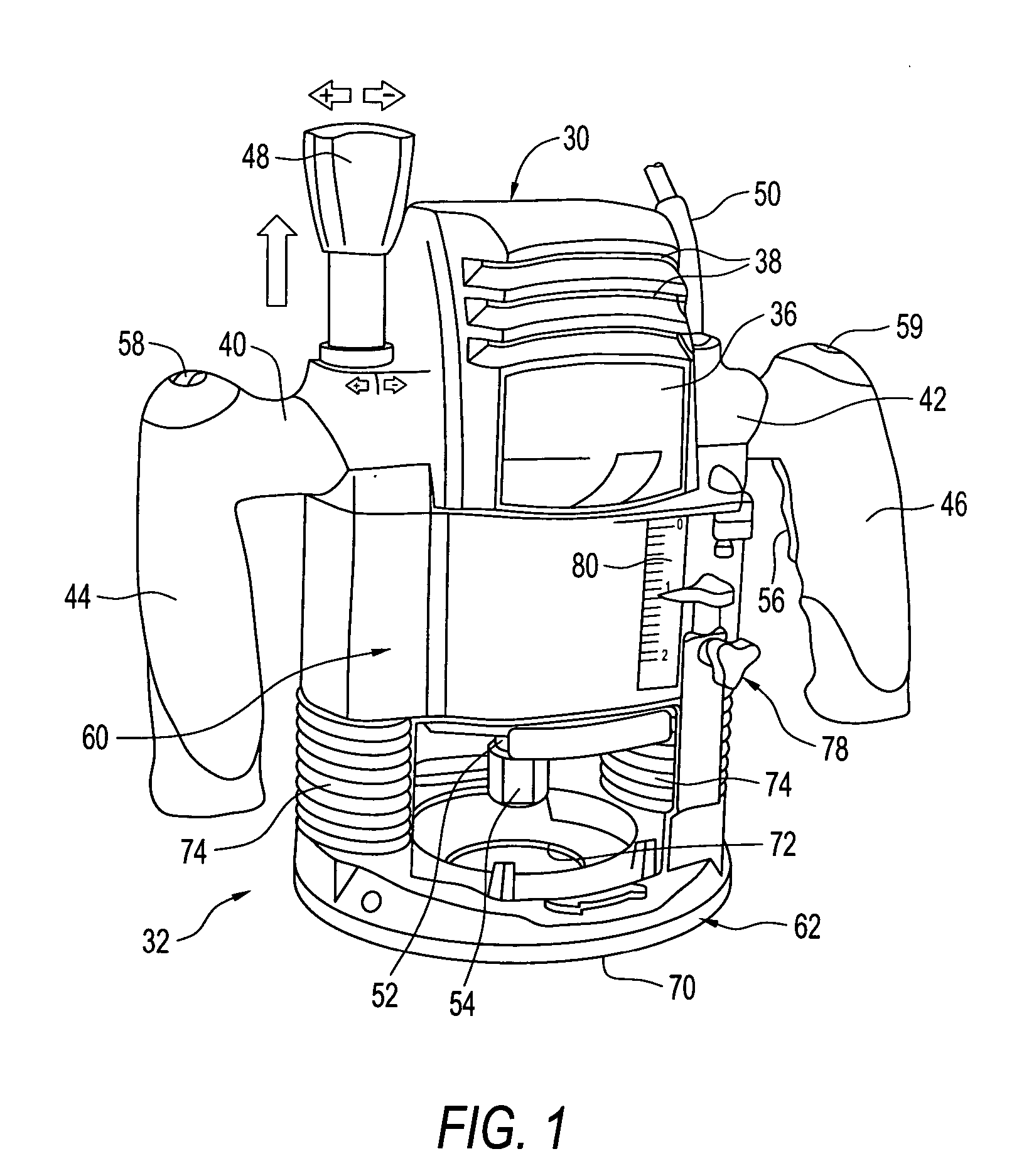
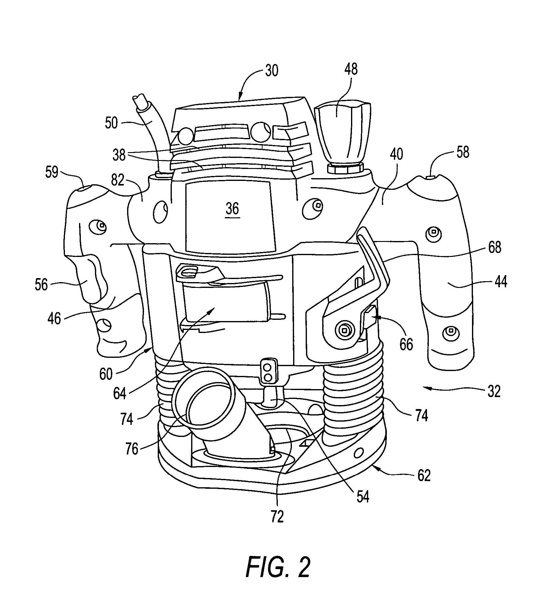
[0032] Broadly stated, the preferred embodiment of the hybrid router of the present invention comprises a motor assembly that can be installed in either one of a fixed base assembly or a plunge base assembly so that the router can operate either as a fixed router or as a plunge router. Referring to the drawings, FIGS. 1 and 2 illustrate a motor assembly, indicated generally at 30, installed in a plunge base assembly, indicated generally at 32, while FIGS. 3 and 4 show the motor assembly 30 installed in a fixed base assembly, indicated generally at 34.

[0033] With regard to the plunge router shown in FIGS. 1 and 2, the motor assembly 30 has a housing 36 that houses a motor (not shown) that is ventilated by air vents 38 located in the front and back of the top portion thereof with the housing merging with left and right horizontal handle portions 40, 42 that also merge with generally vertical left and right handle portions 44 and 46. A rotatable pop-up knob 48 is provided on the left ...


PUM

PropertyMeasurementUnit
depthaaaaaaaaaa
lengthaaaaaaaaaa
circumferenceaaaaaaaaaa

Abstract

A hybrid router is disclosed that is capable of operating as a fixed or a plunge router wherein the preferred embodiment thereof comprises a motor assembly that has a housing containing a motor as well as operating handles attached to the housing and operating controls for operating the motor. The motor assembly can be removably installed in either a fixed base assembly or a plunge base assembly. The preferred embodiment has an adjustment knob that is located on the motor assembly that engages depth adjustment mechanisms of either the fixed and plunge base assemblies when the motor assembly is installed in the respective base assemblies.

Description

BACKGROUND OF THE INVENTION [0001] The present invention generally relates to hand held power tools and more particularly to routers. [0002] Routers are convenient tools that have been used by craftsmen and artisans for decades to perform many woodworking tasks, including cutting decorative shapes and edges in wood and other materials that are conducive to such operations. Routers are generally of two types, fixed base routers and plunge routers. In a fixed based router, the housing is fixed or locked in a position relative to the base after the depth of cut of the tool bit has been set. A plunge router has a housing that is movable relative to a base with the amount of vertical movement being determined by a depth limiting mechanism so that when an operator pushes down on the router to engage the bit into a work surface, it can be locked at the working elevation during operation. [0003] Either type of router can be used free hand by a user or can be mounted to a table and operated ...

Claims


Application Information

Patent Timeline
Patent Type & Authority Applications(United States)
IPC IPC(8): B27C5/10
CPCB27C5/10Y10T409/308176Y10T409/308624Y10T409/306608Y10T409/308736
Inventor FREESE, JOHN B.GUNDERSON, BJORN J.BRUNO, ROBERT H.
Owner CREDO TECH CORP
Learn More