Electromagnetic shield for an induction heating coil

a technology of induction heating coil and electromagnetic shield, which is applied in the direction of active shielding, induction current source, electric/magnetic/electromagnetic heating, etc., can solve the problem of reducing reliability, reducing the lateral movement of the strip in and out of the screen, and exceeding the level of generated magnetic field intensities in the region in which the coil and strip are magnetically coupled

Active Publication Date: 2005-01-13
INDUCTOTHERM INDS
View PDF5 Cites 19 Cited by
  • Summary
  • Abstract
  • Description
  • Claims
  • Application Information

AI Technical Summary

Problems solved by technology

However unless some type of electromagnetic shielding is used, the generated magnetic field intensities in regions beyond the region in which the coil and strip are magnetically coupled may exceed permissible levels.
One disadvantage of the arrangements in FIG. 1 and FIG. 2 is that each screen is closed around the strip, which makes lateral movement of the strip in and out of the screens impossible.
One disadvantage of this method is that an electrically conductive component, namely the decoupling rings, must include a mechanical switch that reduces reliability and increases operational complexity and maintenance.

Method used


Image

  • Electromagnetic shield for an induction heating coil
  • Electromagnetic shield for an induction heating coil
  • Electromagnetic shield for an induction heating coil

Examples


Embodiment Construction

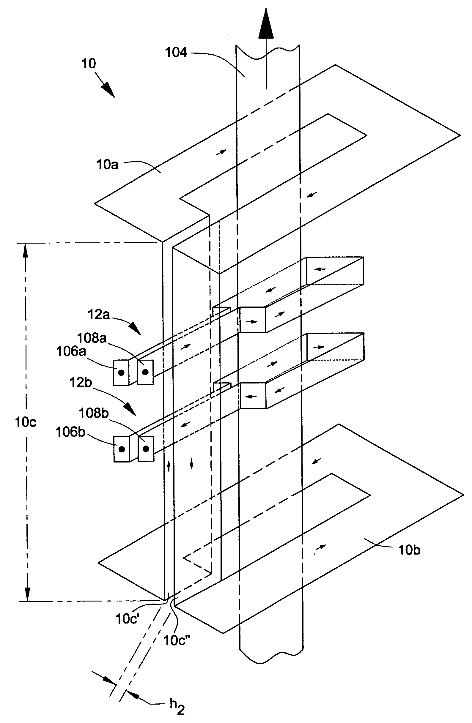
[0016] Referring now to the drawings, wherein like numerals indicate like elements, there is shown in the FIG. 3, one example of the electromagnetic shield or screen 10 of the present invention that forms an electromagnetic shield. The screen comprises first transverse screen element 10a, second transverse screen element 10b, and longitudinal screen element 10c, which connects the first and second transverse elements together as shown in FIG. 3. Longitudinal screen element 10c consists of first and second longitudinal screen sections 10c′ and 10c″ that are substantially parallel to each other and separated by gap h2. In this non-limiting example of the invention, two single turn coils 12a and 12b are suitably connected to one or more ac power sources so that instantaneous ac current flows in opposing directions in the two coils as indicated by the arrows. The coils are disposed between the first and second transverse screen elements of screen 10. A continuous workpiece 104, such as ...


PUM


Abstract

An apparatus and process are provided for reducing the electromagnetic field intensity in selected regions for a field produced when ac current flows through one or more induction coils through which a workpiece moves for induction heating of the workpiece. The electromagnetic shield has transverse screen elements through which the workpiece moves at opposing ends of the one or more induction coils. One or two longitudinal screen elements connect the transverse screen elements.

Description

CROSS REFERENCE TO RELATED APPLICATIONS [0001] This application claims the benefit of U.S. Provisional Application No. 60 / 482,825 filed Jun. 26, 2003, hereby incorporated herein by reference in its entirety.FIELD OF THE INVENTION [0002] The present invention relates to electromagnetic shields or screens used with induction heating coils that inductively heat a workpiece moving through the induction coils. BACKGROUND OF THE INVENTION [0003]FIG. 1 illustrates a single turn induction coil 102 surrounding a metal strip 104 that continuously moves through the coil in the direction indicated by the arrow. Terminals 106 and 108 of coil 102 are connected to a suitable ac power source with instantaneous current flow through the coil as indicated by the arrows. The current flowing through the coil establishes a magnetic field that inductively heats the strip as it passes through the coil. However unless some type of electromagnetic shielding is used, the generated magnetic field intensities i...

Claims


Application Information

Patent Timeline
Patent Type & Authority Applications(United States)
IPC IPC(8): H05KH05K9/00
CPCH05K9/0071H05B6/104H05K9/00
Inventor LOVENS, JEAN
Owner INDUCTOTHERM INDS
Why Eureka
Try Eureka