Thermal response correction system

a correction system and thermal technology, applied in the field of thermal printing, can solve the problems of reducing the density of the output produced by the print head element, and reducing the density of the outpu

Inactive Publication Date: 2005-01-13
TPP TECH LLC
View PDF42 Cites 161 Cited by
  • Summary
  • Abstract
  • Description
  • Claims
  • Application Information

AI Technical Summary

Benefits of technology

[0018] Additional aspects and embodiments of the present invention will be described in more detail below.

Problems solved by technology

One problem with conventional thermal printers results from the fact that their print head elements retain heat after the conclusion of each print head cycle.
This retention of heat can be problematic because, in some thermal printers, the amount of energy that is delivered to a particular print head element during a particular print head cycle is typically calculated based on an assumption that the print head element's temperature at the beginning of the print head cycle is a known fixed temperature.
Further complications are similarly caused by the fact that the current temperature of a particular print head element is influenced not only by its own previous temperatures—referred to herein as its “thermal history”—but by the ambient (room) temperature and the thermal histories of other print head elements in the print head.
This gradual temperature increase results in a corresponding gradual increase in density of the output produced by the print head element, which is perceived as increased darkness in the printed image.
Furthermore, conventional thermal printers typically have difficulty accurately reproducing sharp density gradients between adjacent pixels both across the print head and in the direction of printing.
This problem results from the amount of time that is required to raise the temperature of the print head element to print the black pixel after printing the white pixel.
More generally, this characteristic of conventional thermal printers results in less than ideal sharpness when printing images having regions of high density gradient.
An attempt to apply the thermal history control techniques disclosed above to such a print mechanism may, therefore, produce suboptimal results, because the assumption of equally-sized print intervals would be violated.

Method used


Image

  • Thermal response correction system
  • Thermal response correction system
  • Thermal response correction system

Examples


Embodiment Construction

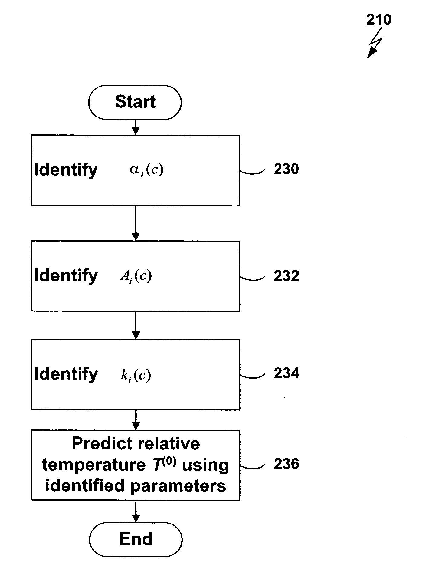
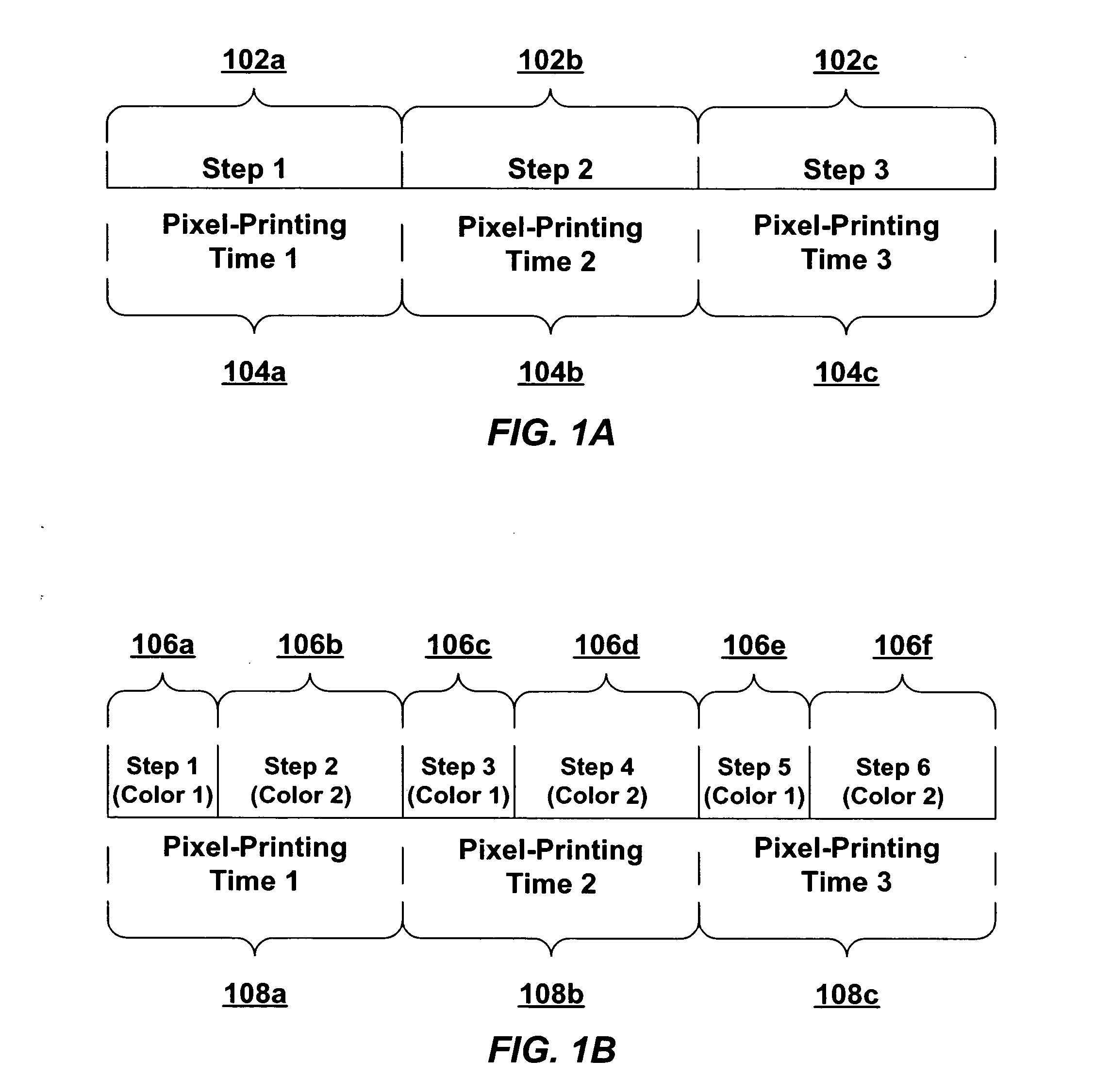
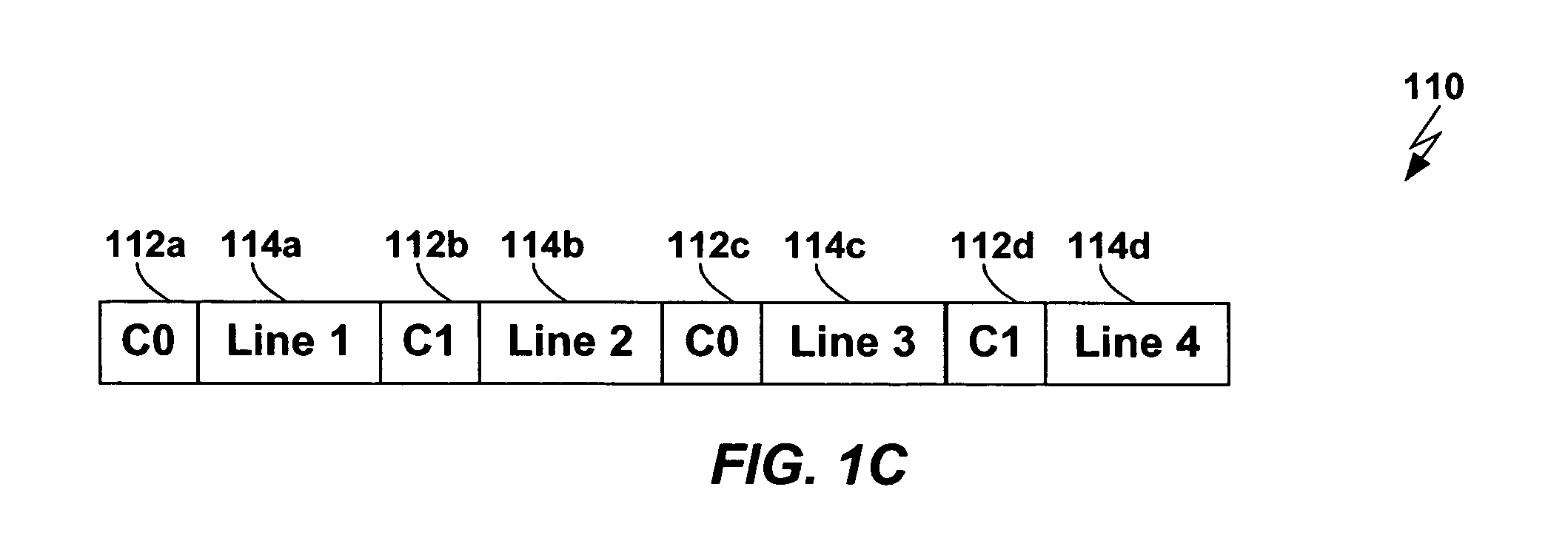
[0028] Techniques are disclosed for performing thermal history control in a thermal printer in which a single thermal print head prints sequentially on multiple color-forming layers in a single pass. Each pixel-printing interval may be divided into subintervals, which may be of unequal duration. Each sub-interval may be used to print a different color. The manner in which the input energy to be provided to each print head element is selected may be varied for each of the subintervals. For example, although a single thermal model may be used to predict the temperature of the print head elements in each of the subintervals, different parameters may be used in the different subintervals. Similarly, different energy computation functions may be used to compute the energy to be provided to the print head in each of the subintervals based on the predicted print head element temperature.

[0029] For example, in the above-referenced patent applications, techniques are disclosed for performin...


PUM


Abstract

Techniques are disclosed for performing thermal history control in a thermal printer in which a single thermal print head prints sequentially on multiple color-forming layers in a single pass. Each pixel-printing interval may be divided into subintervals, which may be of unequal duration. Each sub-interval may be used to print a different color. The manner in which the input energy to be provided to each print head element is selected may be varied for each of the subintervals. For example, although a single thermal model may be used to predict the temperature of the print head elements in each of the subintervals, different parameters may be used in the different subintervals. Similarly, different energy computation functions may be used to compute the energy to be provided to the print head in each of the subintervals based on the predicted print head temperature.

Description

CROSS REFERENCE TO RELATED APPLICATIONS [0001] This application is a continuation-in-part of U.S. patent application Ser. No. 10 / 831,925, filed on Apr. 26, 2004, entitled “Thermal Response Correction System,” which is a continuation-in-part of U.S. patent application Ser. No. 09 / 934,703, filed on Aug. 22, 2001, entitled “Thermal Response Correction System,” which are both hereby incorporated by reference. [0002] This application is related to a copending and commonly owned U.S. patent application Ser. No. 10 / 151,432, filed on May 20, 2002, entitled “Thermal Imaging System,” which is hereby incorporated by reference.FIELD OF THE INVENTION [0003] The present invention relates to thermal printing and, more particularly, to techniques for improving thermal printer output by compensating for the effects of thermal history on thermal print heads. RELATED ART [0004] Thermal printers typically contain a linear array of heating elements (also referred to herein as “print head elements”) that...

Claims


Application Information

Patent Timeline
Patent Type & Authority Applications(United States)
IPC IPC(8): B41J2/36B41J2/365
CPCB41J2/3555B41J2/365B41J2/36G06F3/1204B41J2/07B41J2/2146G06K15/02B41J2/15
Inventor BUSCH, BRIAN D.SAQUIB, SUHAIL S.VETTERLING, WILLIAM T.
Owner TPP TECH LLC
Why Eureka
Try Eureka