
Fluidic MEMS device

a microelectromechanical and fluid technology, applied in microstructural devices, microstructure technology, printing, etc., can solve the problems of fluid leakage and/or fracture of packaging materials, incompressible fluids, and low compressibility

Inactive Publication Date: 2005-01-20
HEWLETT PACKARD DEV CO LP
View PDF16 Cites 58 Cited by
  • Summary
  • Abstract
  • Description
  • Claims
  • Application Information

AI Technical Summary

Problems solved by technology

Such hermetic MEMS packages may comprise rigid and / or brittle materials.
The fluid may also be incompressible or have a very low degree of compressibility.
As a result, thermal excursions may result in an increase of fluid pressure in the inner cavity which may lead to fluid leakage and / or fracture of the packaging materials.

Method used


Image

  • Fluidic MEMS device
  • Fluidic MEMS device
  • Fluidic MEMS device

Examples


Embodiment Construction

[0014] In the following detailed description and in the several figures of the drawing, like elements are identified with like reference numerals.

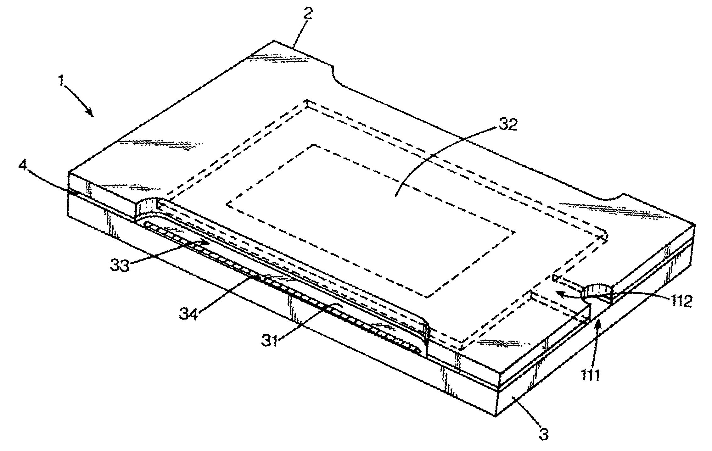
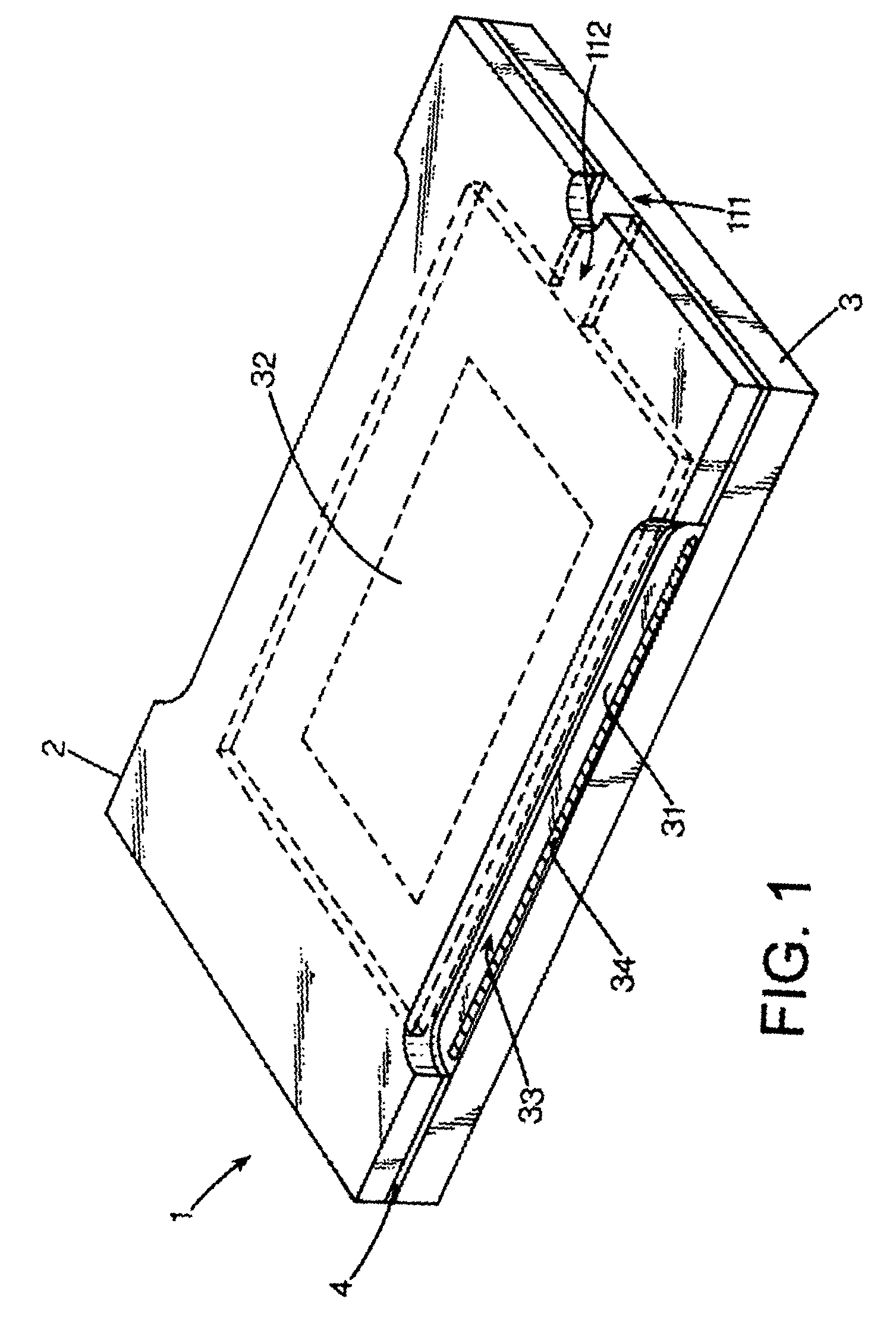
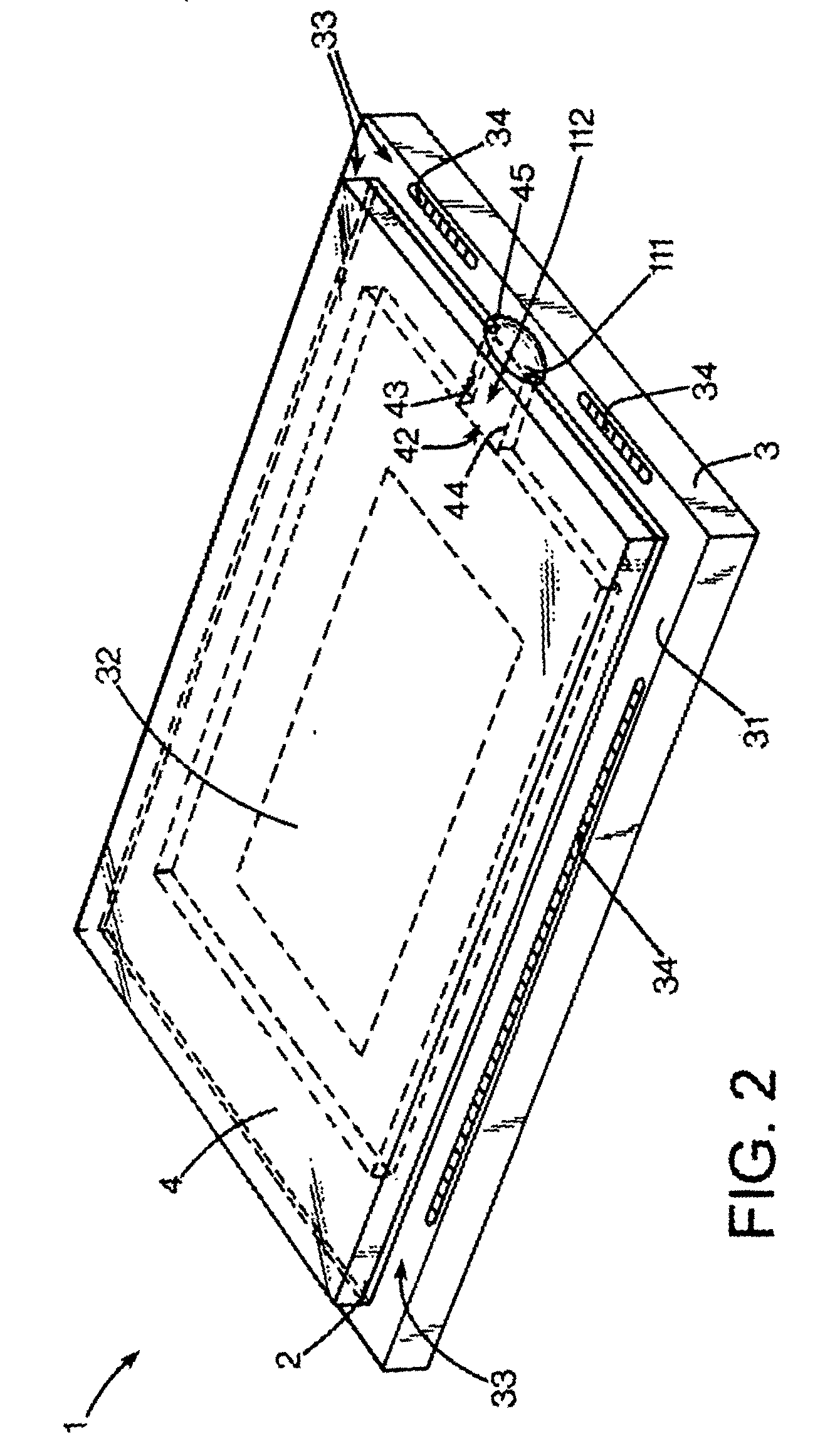
[0015]FIGS. 1 through 4 illustrate exemplary embodiments of MEMS package assemblies suitable for use as fluidic MEMS devices. A MEMS assembly or package 1 includes a cover plate 2, a substrate 3 and a bond ring 4. A primary face 21 (FIG. 3) of the cover plate 2 is attached to a primary surface 31 of the substrate by a bond ring 4. The cover plate 2 may be an optical window or aperture and may comprise silicon, glass, plastic, metal or metal alloys, such as Kovar (TM), or other suitable material. The substrate 3 may be a silicon substrate and may have a MEMS structure 32 fabricated on the primary surface 31. The bond ring 4 may be an inorganic bond ring. The cover plate may be smaller than the substrate and may define exposed portions 33 on the substrate which are not covered by the cover plate. Electrical bonding pads 34 for making electr...


PUM

PropertyMeasurementUnit
Forceaaaaaaaaaa
Pressureaaaaaaaaaa
Solubility (mass)aaaaaaaaaa

Abstract

A MEMS package comprises a substrate and a cover plate. A MEMS structure is fabricated on a surface of the substrate. The cover plate may be bonded to the substrate by a bond ring. The cover plate, the bond ring and the substrate may define an inner cavity. The cover plate, the substrate and a breach in the bond ring may define a fill port.

Description

BACKGROUND OF THE DISCLOSURE [0001] Certain fluidic micro-electro-mechanical systems (MEMS) applications include fluid in a hermetically sealed inner cavity of a MEMS package. Such hermetic MEMS packages may comprise rigid and / or brittle materials. The volumetric expansion rate of fluids hermetically sealed in MEMS packaging, upon increases in temperature, may be as much as 20 to 100 times greater, for example, than the expansion rate of the inner cavity of the package based on the linear expansion rate of the packaging materials. The fluid may also be incompressible or have a very low degree of compressibility. As a result, thermal excursions may result in an increase of fluid pressure in the inner cavity which may lead to fluid leakage and / or fracture of the packaging materials. SUMMARY OF THE DISCLOSURE [0002] An exemplary embodiment of a MEMS package comprises a substrate and a cover plate. A MEMS structure is fabricated on the substrate. The cover plate may be bonded to the sub...

Claims


Application Information

Patent Timeline
IPC IPC(8): B81B7/02B81B7/00B81C1/00B81C3/00H01L23/24
CPCB81B7/0061
Inventor SMITH, MARK A.BOUCHER, WILLIAM R.HALUZAK, CHARLES C.
Owner HEWLETT PACKARD DEV CO LP
Features
  • Generate Ideas
  • Intellectual Property
  • Life Sciences
  • Materials
  • Tech Scout
  • Unparalleled Data Quality
  • Higher Quality Content
  • 60% Fewer Hallucinations
Learn More